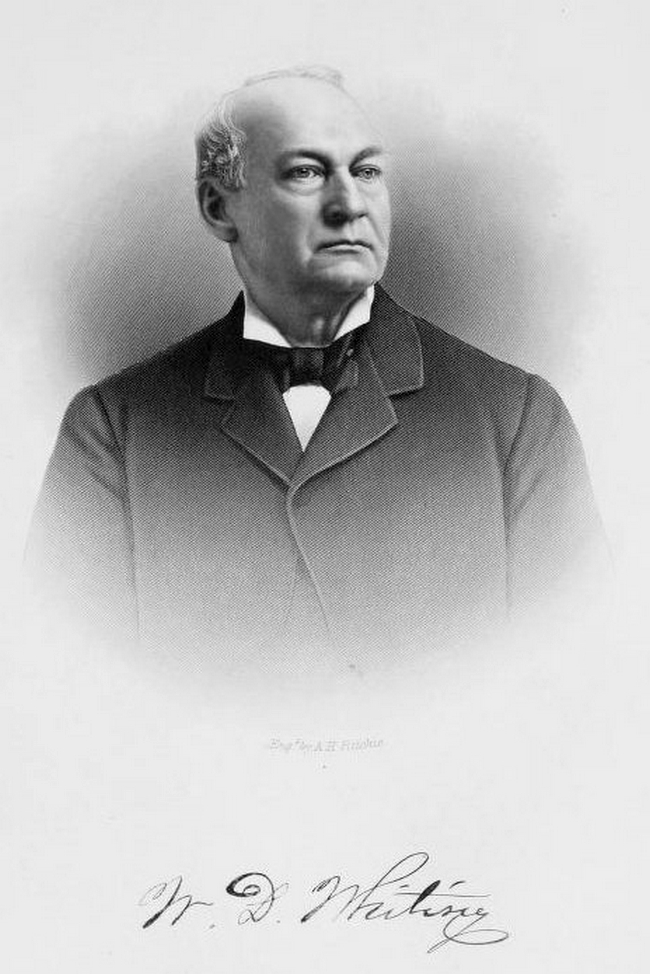
William Dean Whiting
- Born: 23 Dec 1815, Attleboro MA
- Marriage (1): Rebecca Damon Butterfield on 17 Dec 1839 in Dedham MA
- Died: 25 Nov 1891, Attleboro MA
General notes:
Silversmith and jeweler
Events in his life were:
- Apprenticed: Draper & Tifft, about 1835, in North Attleboro MA. 12

- Partnership: Albert Crandall Tifft, in 1840-1853, in North Attleboro MA. As TIFFT & WHITING. On January 1, 1853, Whiting bought out his partner's interest for $100,000 in cash. 12
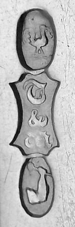
- He appeared on the census in 1850 in Attleboro MA. Listed as a jeweler.

- He worked circa 1853-1855 as a silversmith in Attleboro MA as W. D. WHITING & Co.
- Partnership: ? Gooding, circa 1855-1858, in North Attleboro MA. As WHITING & GOODING. 12
- He appeared on the census in 1855 in Attleboro MA. Listed as a manufacturing jeweler.
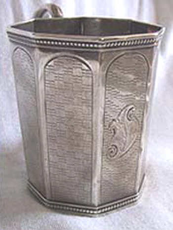
- Example: Cup by TIFFT & WHITING, circa 1860, in Private Collection. H: 3"
d: 2 1/2"
Engraved in cartouche "Rosalie Berens Peterson"
- He appeared on the census in 1860 in Attleboro MA. Listed as a jewelry manufacturer.
- Partnership: William Cowan and ? Bowen, in 1864-1866, in North Attleboro MA. As WHITING, COWAN, & BOWEN 12
- Partnership: with various others, after 1866, in North Attleboro MA. As WHITING MANUFACTURING Co. In 1875 the company factory burned down and was re-built in Newark NJ. In 1924 the firm was purchased by Gorham Company. 12
- He appeared on the census in 1870 in Attleboro MA. Listed as a manufacturer of silverware.
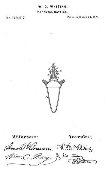
- He was issued patent number 149,017 on 24 Mar 1874
WILLIAM D. WHITING, OF NORTH ATTLEBOROUGH, MASSACHUSETTS.
IMPROVEMENT IN PERFUME-BOTTLES.
Specification forming part of Letters Patent No. 149,017 dated March 24, 1874; application filed July 7, 1873.
To all whom it may concern:
Be it known that I, W. D. WHITING, of North Attleborough, Bristol county, in the State of Massachusetts, have invented certain new and useful Improvements relating to Vinagrettes or Perfume-Bottles, of which the following is a specification:
The parts may be made of silver or gold, and richly chased or otherwise decorated in accordance with modern taste. I will describe only the parts to which the invention applies, it being understood that the vessel may be of any shape beneath. As usually constructed the device is small, and provided with ears, by which it may be slung. The escape of the odor is controlled by a valve and spring capable of being depressed by the finger or thumb. When open the odor is diffused through a number of perforations.
The following is a description of what I consider the best means of carrying out the invention.
The accompanying drawing forms a part of this specification, and represents a central vertical section.
Referring thereto, A is the main body of the vessel, and B is a mouth-piece or nozzle secured thereon by means of the screw-threads & a. It is provided with numerous holes in its upperface. The largest central hole carries a stem, D, which is fluted, and also allows odor to escape through its flutings whenever the attached valve C is depressed. E is a piece forming the valve - seat. It fits tightly in the slightlytapered interior of the neck of the vessel A, and is formed with a flange at the top, which is pressed upon by an internal shoulder in the mouth-piece B, and thus held firmly down to form, a tight union. The valve C D is pressed upward by a coiled spring, G, contained within the mouth-piece B. It abuts at its lower end on the upper face of the seat-piece B, and near its upper end on a cross-pin, d, fitted in the valve-stem D. The outer end of the valvestem. D may be receive any suitable ordinary knob, as indicated by D'. Under ordinary conditions the tension of the spring G holds the valve C tightly up to its seat and there is no escape of the volatile contents of the bottle.
Whenever it is desired that the odor shall escape, the operator depresses the valve C by acting on the knob D'. This makes an opening through the valve-seat in the flutings of the stem D, and the odor, thence escaping into the mouthpiece B, is mingled with air and diffused into the atmosphere through the apertures therein. The removal of this mouthpiece B by unscrewing liberates the seat-piece E by ceasing to longer press down with the retaining shoulder upon its flange. The removal of the knob D1 from the stem D allows the valve and seat-piece with its spring and cross-pin to be removed from the piece B.
I claim as my invention—
The removable seat-piece E adapted to be confined by the internal shoulder in the openwork screw-cap B, in combination with such cap and with the bottle A, valve C, rod D, and spring G, arranged for joint operation, as and for the purposes specified.
In testimony whereof I have hereunto set my hand this 9th day of June, 1873, in the presence of two subscribing witnesses.
William D. Whiting
Witnesses:
Charles Selden
John C. Purkis
- He was issued patent number 152,266 on 23 Jun 1874
WILLIAM D. WHITING, OF ATTLEBOROUGH, MASSACHUSETTS, ASSIGNOR TO THE WHITING MANUFACTURING COMPANY.
IMPROVEMENT IN MANUFACTURE OF SPOONS.
Specification forming part of Letters Patent No. 152,266, dated June 23, 1874; application filed March 13, 1874.
To all whom it may concern:
Be it known, that I, WILLIAM D. WHITING, silversmith, of Attleborough, Bristol county, Massachusetts, have invented a certain Improved Method of Manufacture of Spoons and analogous articles, of which the following is a specification:
It has long been desired to produce perfect spoons by a small number of simple operations. I have invented means of overcoming some of the most serious difficulties, and am able to stamp spoons completely formed and set at a single operation, and to clip them complete at another, so as to involve very little labor or skill. My method involves the employment of larger blanks than usual, but the loss from remelting the metal thus used is insignificant compared with the economy in the other points.
I can, by my method, produce spoons richly decorated in cameo on both faces of the handle, and with the bowl perfectly dished, without wrinkles. The method involves some laws applicable both iu coining and sheet-metal raising.
It has been attempted to stamp spoons complete; but no one, so far as I am aware, has so wrought that such spoons could be afterward clipped, like sheet-metal shells, by a single operation in a pair of clipping-dies.
Referring now principally to the handle, there is almost necessarily, when the spoon is struck from a sufficiently large blank, to completely fill the pattern, a fin or thin selvage extending out from the edge beyond the boundary of the spoon. One of the difficulties in clipping such spoons as ordinarily struck lies iu the necessity for making the plunger or male clipping-die extend down along the edge of the stamped spoon to reach the fin, and act on it directly. If such extension is sufficiently wide to give strength it involves the clipping out of a piece much larger than the spoon. Without such extension of the plunger down the edge, and with a plunger actingonly 0n the edge, there is a liability to the curling upward of the pin, and a contortion of the metal, and dragging and abrading in the act of cutting off the fin. In some modes of working which have been attempted, a difficulty is experienced in placing the spoon in the right position for accurate shearing. I have done much to overcome all these difficulties, by simply causing the fin to extend out from, the edge of the upper face of the spoon instead of extending out from a line at or near the middle of the thickness of the spoon. Referring now to the bowl, a difficulty, as ordinarily conducted, lies in the tendency to crinkling at the edge of the bowl. This is so serious as in many cases to induce the "dapping" of this portion by a great number of gentle blows, holding the spoon and moving it by the hand. I have discovered that the crinkling may be overcome in the rapid stamping process, by so constructing the dies as to compress and thin the metal only along a narrow margin, immediately adjacent to the edge of the spoon, and to leave a liberal quantity of stout metal in the blank outside thereof.
The following is a description of what I consider the best means of carrying out the invention. The accompanying drawings form a part of this specification.
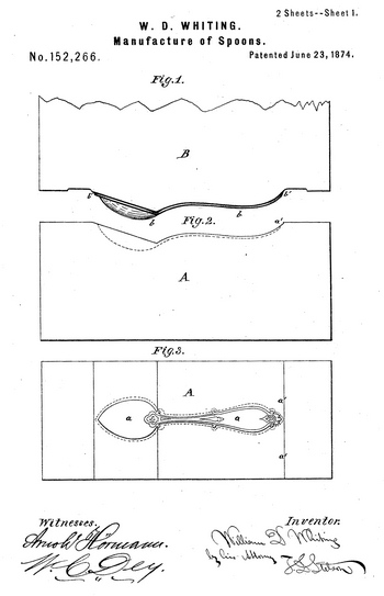
Figures 1, 2, 3, 0, 7, 8, and 9 represent the stamping-dies. Fig. 1 is a side elevation of the upper stamping-die; Fig. 2, a corresponding view of the lower stamping-die; Fig. 3, a plan view of the latter. Figs. 4, o, and 10 represent the clipping-dies, by which the previously-stamped and set spoon is cut out from the broad margin which I leave around it. Fig. 4 is a central longitudinal section of the lower part of the upper clipping-die, sometimes called a plunger. Fig. 5 is a corresponding section of the lower clipping-die. The clipping-dies, Figs. 4 and 5, are represented in the proper relation to each other for working together. Fig. 6 is a transverse section through the bowl of the spoon, iu the act of being formed or raised in the stamping-dies. It represents an early stage iu the raising process. Fig. 7 is a corresponding view, representing a more advanced stage. Fig. 8 is a corresponding view representing the raising completed. Fig. 9 is a transverse section through the handle of the spoon,in the act of being stamped in the stamping-dies. The succeeding figure, Fig. 10, represents the same in the act of being clipped in the clipping-dies. Both these Figs. 9 and 10 are on a larger scale.
Similar letters of reference indicate like parts in all the figures.
A is the bed-die, having the hollow for the bowl, and having the space for nearly the entire handle sunk in its curved face, with the proper devices produced therein in intaglio for the decoration. B is a moving die, having a surface, b, of corresponding form to the spoon, and a little larger, projecting a little more than the thickness of a spoon below the general face. This projecting or raised portion on the die B may be also formed with decorative devices. The edge of the raised surface b is beveled, as shown by b'. M is a rectangular piece of sheet metal, previously graduated in thickness by rolling, so that the ends are just sufficiently thinner than the middle, as has long been practiced in spoonmaking.
In operating, this blank is placed with one end abutting a shoulder, a', of the die A. On the powerful descent of the die B, by being carried in a heavy hammer, or otherwise, a spoon is completely shaped and set.
The faces of the clipping-dies C D are shaped to correspond with the set of the spoon. The face of the upper die or plunger D corresponds in outline to the outline of a spoon. The lower die, C, has a corresponding cavity. When the blank prepared in the dies A B is applied in the clipping-dies C D the cavity in the lower die C receives nearly the whole thickness of the spoon, and bears around its entire edge, fitting fairly against the under face of the fin. Now, the upper clipping-die D, being depressed, smoothly shears out the spoon. The slightly-enlarged pattern b b' on the upper stamping-die B compresses the metal and reduces its thickness along a little breadth— say, one-thirty-second of an inch wide—quite around the edge of the spoon; but the rest of the metal outside of the spoou is left with its full original thickness.
By my mode of operation, while the material of the bowl is being drawn inward, and the material along its rim is being compresed together, the stout portion of the blank outside of the spoon supports, it against wrinkling.
I have determined by experiment that, without involving any destructive waste, I can by these dies form entire spoons from these large blanks very completely.
The width of the rectangular blanks may be made less than represented; but a contraction beyond a certain breadth will involve a risk of spoiling the spoon. Having a due regard for economy, I prefer to give the sheet metal a breadth about one and a half times the extreme breadth of the finished bowl.
The stout metal or unaffected outer portion of the blank is kept in the proper position during the stamping process by the form of the stamping-dies, which are adapted to hold the said blank metal against being curled up, so that the struck-up spoon, with the stout outside metal attached, comes from the stampingdies bent to the general longitudinal curvature of the spoon; but not much bent or curled transversely. When in the shearing-dies the stout metal outside performs a further useful function in aiding to keep the fin in the proper position during the shearing.
Although I have described the process as applying to spoons of the ordinary form, and known as simply tea-spoons, and have experimented on such, I believe my invention may be applied with success in the manufacture of the variously-scalloped devices known as sugar-spoons, fruit-spoons, or the like, and also in the manufacture of ladles, forks, and other articles of table use, either of silver or other malleable metals.
I have designated the entire space for the spoon, including both the handle and bowl, which is sunk in the lower die by the single letter a.
Some of the advantages due to certain features of the invention may be separately enumerated as follows: First, by reason of the fact that the selvage is partially pinched off and extended out from the edge of one face, instead of, as usual, from the middle of the thickness, I am able to use a clipping-die having a thick and strong form, as shown by D; second, by reason of the raised pattern b, b' extending a little outside of the edge of the sunk pattern in the opposite die, as shown, leaving a space outside for the thick stout metal in the blank to remain unaffected, I am able to support the metal of the bowlby such stout outside metal, and cause it to stretch in the bottom of the bowl without much contracting of the rim, and without danger of forming wrinkles; and am also able to support the thin fin against being bent up under the action of the shearing-dies; third, by reason of the thin fin or selvage extending from the edge of one face, and also the stout border outside of such compressed narrow selvage, I am able to form the spoon complete at a single operation on one pair of stampingdies, and to conveniently place it in position and treat it by thick-edged and durable dies in clipping it.
I claim as my invention—
1. The within-described method of striking a spoon in dies, so as to leave a broad and thick margin outside of a thin border or selvage extending along the edge, as and for the purposes specified.
2. The method of forming, setting, and clipping spoons by stamping in form, with a thinned selvage connecting thereto along the edge of one face, and also preserving a stout border outside of such thin selvage, so as to clip it complete in stout-edged dies at a single succeding operation, as specified.
In testimony whereof I have hereunto set my hand this 6th day of March, 1874, in the presence of two subscribing witnesses.
W. D. Whiting
Witnesses:
Thomas D. Stetson
F. Dickenson, Jr.
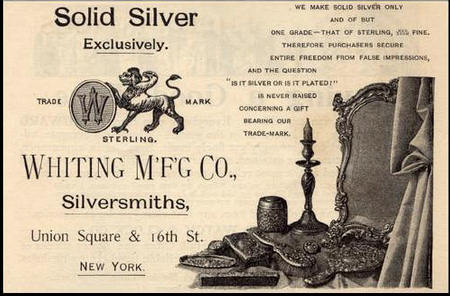
- Example: Tradecard, circa 1880, in Private Collection. For WHITING MANUFACTURING & Co.
- He appeared on the census in 1880 in North Attleboro MA. Listed as a manufacturer of silverware.
William married Rebecca Damon Butterfield, daughter of Pitts Butterfield and Lucy Damon, on 17 Dec 1839 in Dedham MA. (Rebecca Damon Butterfield was born on 8 May 1818 in Dedham MA and died on 10 Jan 1894.)
|


