William Worcester Lyman
- Born: 29 Mar 1821, Middlefield CT
- Marriage (1): Roxanne Griswold Frary on 5 Sep 1841
- Died: 15 Nov 1891, Meriden CT
General notes:
Pewtersmith
Events in his life were:

- Apprenticed: GRISWOLD & COUCH, in 1836-1841, in Meriden CT. Griswold was Lyman's step-father.
- He worked in 1842-1844 as a pewtersmith in Meriden CT having purchsed the business of his former master.
- Partnership: Ira Couch, in 1844-1845, in Meriden CT. As LYMAN & COUCH, britannia spoon manufacturers.
- Partnership: William Henry Bull, circa 1845, in Meriden CT. As LYMAN & BULL.
- Partnership: Ira Couch and George Bull, in 1845-1849, in Meriden CT. As BULL, LYMAN & COUCH.
- Appointed: State Representative, in 1849, in Meriden CT.
- He worked in 1852-1880 as a pewtersmith in Meriden CT
In addition to his general line of goods, Lyman is credited with inventing the first practical can opener, using a rotary cutting wheel on a central pivot. He also patented the "Lyman Fruit Jar" with an improved lid seal that was sold in vast quanities.
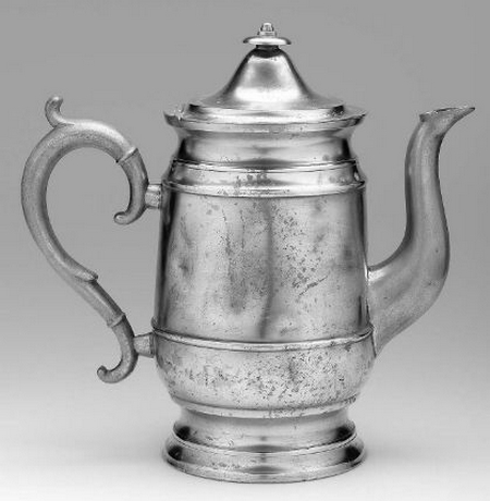
- Example: Teapot, circa 1852, in Museum of Fine Arts, Boston. H: 10 1/4
d: 5 1/4" (of base)
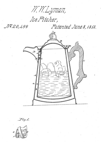
- He was issued patent number 20,499 on 8 Jun 1858
W. W. LYMAN, OF WEST MERIDEN, CONNECTICUT.
REFRIGERATING-PITCHER.
Specification of Letters Patent No. 20,499, dated June 8, 1858.
To all whom it may concern:
Be it known that I, W. W. LYMAN, of West Meriden, in the county of New Haven and State of Connecticut, have invented a new and useful Improvement in Valves by which the Nozzles of Ice or Refrigerating Pitchers are Effectually Closed; and I do hereby declare that the following is a full, clear, and exact description of the same, reference being had to the annexed drawings, making a part of this specification, in which—
Figure 1, is a vertical section of a pitcher with my improvement applied to it. Fig. 2, is a detached perspective view of ditto.
Similar letters of reference indicate corresponding parts in the two figures.
This invention consists in having the valve formed with double sides, or, in other words, having it made hollow and of a thickness or width corresponding to that of the pitcher to which it is attached, said valve being fitted in the pitcher at the throat of the nozzle, and so arranged as to open and close by its own gravity as the pitcher is tilted and replaced in an upright position and form, when closed a tight joint.
To enable those skilled in the art to fully understand and construct my invention I will proceed to describe it.
A, represents a pitcher formed with double sides a, a-, having a clear air space 5, between. B, is the lid of the pitcher also constructed double to form a chamber within.
The lid is hinged to the pitcher as usual. C, is the handle of the pitcher and D, is the nozzle. The above parts are all of usual construction and therefore do not require a minute description.
E, is a valve which is formed of two sides c, c', connected by an end piece d, which extends all around the valve and forms its edge. The valve is equal in thickness to the pitcher at the point where it is placed, and the upper end of the valve is hinged to the pitcher as shown at e. This valve is fitted in the pitcher at the throat of the nozzle D, as shown clearly in Fig. 1. The front side plate e, of the valve projects a trifle beyond the end piece d, so as to form a lip or shoulder f, and a lip or shoulder g, is formed on the pitcher all around the valve seat so that when the valve is closed the lip or shoulder f, laps over the edge of the orifice in which the valve is fitted, the inner side c', of the valve when it is closed bears against the lip or shoulder g. The valve when closed therefore forms a tight or close joint, an important feature in an ice or refrigerating pitcher, for considerable external air is admitted into the pitcher through the nozzle when it is not perfectly stopped.
The pitcher A, is of conical form and consequently the valve will, when the pitcher is in an upright position remain closed by its own gravity, the valve opening by the same cause when the pitcher is tilted.
In consequence of having the valve formed with double sides it not only effectually stops the nozzle when closed and serves in common with the other double portions of the pitcher as a nonconductor, but it also possesses sufficient weight to operate quickly, no additional weight therefore is required as would be the case were a single plate or thin valve used.
Having thus described my invention. I would state that, I make no claim to a valve in the end of the nozzle, or on the lid of a pitcher, as valves have heretofore been placed there—nor do I claim a single valve located anywhere but—
What I claim as new and desire to secure by Letters Patent, is,
In the manufacture of ice pitchers the particular location of the valve viz: in the throat of the nozzle, when said valve shuts into instead of against the opening and is constructed with double sides, or, made hollow, provided with a projecting lip or shoulder f, and having its seat provided with a lip or shoulder g, substantially as shown and described.
W. W. Lyman
Witnesses:
Nelson Merriam
Hiram Foster
- He appeared on the census in 1860 in Meriden CT. Listed as a manufacturer.
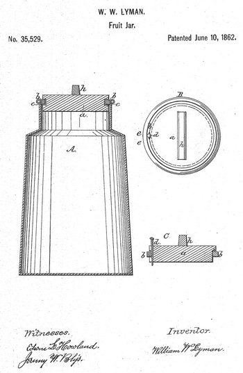
- Patent: 33,529, on 10 Jun 1862. WILLIAM W. LYMAN, OF WEST MERIDEN, CONNECTICUT.
IMPROVED FRUIT-CAN.
Specification forming part of Letters Patent No. 33,529, dated June 10, 1862.
To all whom it may concern:
Be it known that I, WILLIAM W. LYMAN, of West Meriden, county of New Haven, and State of Connecticut, have invented certain new and useful Improvements in Fruit-Cans; and I do hereby declare that the same is described and represented in the following specification and drawings in such a manner as to enable others skilled in the art to make and use the same thereform.
I will therefore proceed to describe its construction and operation, referring to the drawings, in which the same letters indicate like parts in each of the figures.
The nature of this improvement in fruit-cans consists in providing therefor a properly formed stopper, made of suitable material to receive and hold an, elastic packing-ring, so that when the can is filled in the desired manner with fruit, &c., while in a warm or heated state, and the stopper inserted to close the can, it (the stopper) will be drawn downward to fill
the vacuum produced by the cooling of the fruit, &c., and thereby exhaust the air and render it air-tight until wanted for use; and, further, in providing for the easy removal of the stopper by inserting a pointed instrument between the elastic ring and the stopper proper, or inserting said instrument between the elastic
ring and the neck of the can, to produce vent to relieve the downward compression thereof.
In the accompanying drawings, A is a sectional elevation of the can made much in the usual form, of britannia or other suitable material.
B is a top view of the stopper. C is a sectional edge view thereof.
a is the stopper.
b is the elastic ring.
c is a groove formed in the edge of the stopper to receive and hold in place the elastic ring b.
d is a pointed instrument designed to be used for the purpose of inserting into the can between the ring & and the stopper a, or between the ring & and the neck of the can, to form openings e on each side of said instrument to
relieve its tenacity by allowing the passage of, air through said openings.
h is a haft formed on the stopper for extracting it from the can.
By the use of this improvement it will be seen that fruit can be more easily secured without the fear of injury thereto, and can be opened for use with the least amount of trouble, and is always ready for use and not liable to be out of order or to be injured.
I believe I have shown the nature of my improvement and its mode of construction so as to enable a person skilled to make and use the same.
What I claim, therefore, and desire to secure by Letters Patent, is—
Producing the openings e, in combination with the stopper a and ring b, substantially in the manner and for the purpose described.
Wm. W. Lyman
Witnesses:
Edwin L. Howland
Jeremy W. Bliss
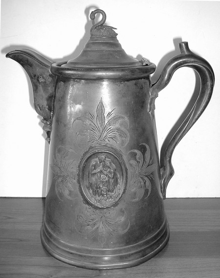
- Example: Water pitcher, circa 1867, in Private Collection. H: 12"
dia: 7 1/2" (of base)
Engraved "Presented to M. Cort Dec 25, 1867"
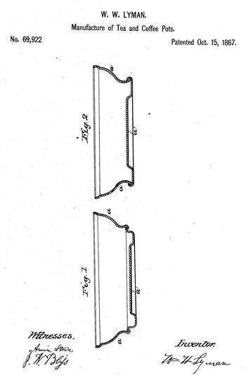
- Patent: 69,922, on 15 Oct 1867. WILLIAM. W. LYMAN, OF WEST MERIDEN, CONNECTICUT, ASSIGNOR TO THE MERIDEN BRITANNIA COMPANY, OF SAME PLACE.
Letters Patent No. 69,922, dated October 15, 1867.
IMPROVEMENTS IN THE MANUFACTURE OF TEA AND COFFEE-POTS.
To All Whom It May Concern:
Be it known that I, WILLIAM W. LYMAN, of West Meridcn, county of New Haven, and State of Connecticut have invented certain new and useful improvements in the Manufacture of Tea and Coffee-Pots; and to enable others skilled in the art to make and use, I will proceed to describe the same by referring to the drawing, in which the same letters indicate like parts in each of the figures.
The nature of this improvement consists in locking a hard metal bottom, such as copper &c., to the body of a Britannia tea or coffee-pot.
The invention consists further in locking the edge of a hard metal bottom on to the lower edge of a Britannia body of a tea or coffee-pot.
The invention consists further in locking the lower edge of a Britannia body on to the edge of a hard metal bottom of a tea or coffee-pot. In the accompanying drawings—
Figures 1 and 2 are vertical section views of the bottom and base of a tea or coffee-pot. a is the base, a' is the bottom. The base a is made of soft metal, commonly called Britannia. The bottom a' is made of hard metal, as copper, &c. In fig. 1, the lower edge of the base a is turned or locked over the edge of the bottom. In fig. 2, the outer edge of the bottom is turned or locked over the lower edge of the base. The process by which this improvement is effected will be understood from the following: A block or chuck is fitted to a spindle, (as the spindle of a lathe.) The lower part of the body of the pot is fitted thereto, and the bottom a' is placed in its proper position against the lower edge of the body, and held in that position by. a back pressure or centre pressure. Thus the edge of the bottom, or the edge of the body is spun or turned down firmly, one upon the other, by the (spinning process) use of pressure of a proper tool, as a planisher or knurling-tool, or what are commonly called spinning-tools; or, in other words, one part is spun down upon the other by the spinning process, tints producing a perfect joint, giving thereto a finished symmetrical appearance.
A very important advantage is derived front this mode or process of uniting the body and bottom of a pot. There is less liability of melting the body in the process of soldering, the soldering can be prosecuted with greater rapidity, and with less liability of melting the Britannia body, and it is also believed that a good joint can be produced without soldering. They may therefore be united with or without solder. Thus a cheaper, better, and more desirable article is produced thereby.
I believe I have thus shown the nature, construction, or process by which this improvement is effected, so as to enable others skilled to practise the same.
What I claim, therefore, and desire to secure by Letters Patent, is—
Uniting a hard metal bottom with a soft metal or Britannia body of a tea or coffee-pot, substantially as described.
I claim a tea or coffee-pot, substantially as described.
Wm. W. Lyman
Witnesses:
Annie Stone
J. W. Bliss
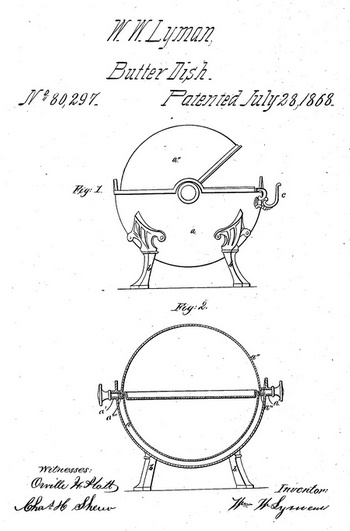
- He was issued patent number 80,297 on 28 Jul 1868
WILLIAM W. LYMAN, OF WEST MERIDEN, CONNECTICUT, ASSIGNOR TO MERIDEN BRITANNIA COMPANY.
Letters Patent No. 80,297, dated July 28, 1868.
IMPROVED BUTTER-DISH.
To All Whom It May Concern:
Be it known that I, WILLIAM W. LYMAN, of West Meriden, county of New Haven, and State of Connecticut,
have invented certain new and useful Improvements in Butter-Dish; and to enable others skilled in the art to make the same, I will proceed to describe, referring to drawings, in which the same letters indicate like parts in each of the figures.
The nature of this invention consists in securing and partially rotating the cover of a butter-dish, by means of right and left-hand screw-threads, fulcrum-pins, or actuating-fulcrum pins, having right and left-hand screw-threads cut or formed on their inner ends, whereby the cover can be freely actuated, and be easily and quickly removed and replaced, as desirable, which cannot be readily performed where the fulcrum and cover-joint are secured together by a pin, as in the common way.
In the accompanying drawings—
Figure 1 is a side elevation of a butter-dish having this improvement.
Figure 2 is a section front elevation of the same.
a is the body of the dish.
a' are joint formations secured to the body of the dish.
a" is a partially-rotating half-globe cover.
a'" are joint formations secured to opposite edges of said cover.
b are feet which support the dish.
c are knife-brackets secured to one side of the body of the dish.
Thus far the dish is constructed substantially in the common way.
Now, instead of putting a straight smooth fulcrum-pin through the joint formations, and securing the inner ends thereof in the cover-joints by a pin, in the common way, I employ right and left-hand screw-threads, cut or formed upon the inner ends of the actuating-fulcra, which screws turn into the joints of the cover in the direction it turns to cover the dish. As there is only a slight effort of the aetuating-fulcrum required to start or turn the cover down, there can be very little or no liability of the screws working loose; and when it is desirable to remove the cover from the dish, it is only necessary to turn but the screws, by turning them in the direction the cover moves in turning off from the dish. Thus the cover may be removed and replaced without let or hindrance, whenever it may be desirable to do so.
I am thus enabled to cheapen the manufacture, and to produce a better and more desirable article for use and trade.
I believe I have thus shown the nature, construction, and advantage of this my improvement, so as to enable others skilled in the art to make and use the same therefrom.
What I claim, therefore, and desire to secure by Letters Patent, is—
The right and left-hand screw-actuating fulcrum, in combination with the cover a" and body a, constructed and operating substantially as and for the purpose described.
Wm. W. Lyman
Witnesses:
Orville H. Platt
Chas. H. Shaw
- He appeared on the census in 1870 in Meriden CT. Listed as a fruit jar manufacturer.
- He appeared on the census in 1880 in Meriden CT. Listed as a metal manufacturer.
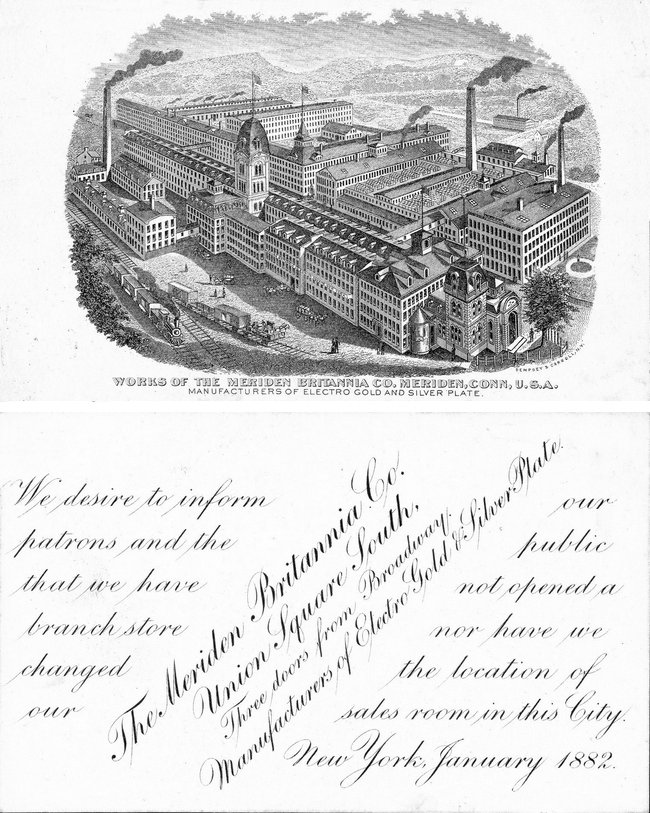
- Example: Trade card for the MERIDEN BRITANNIA Co., in 1882, in Private Collection.
William married Roxanne Griswold Frary, daughter of James Frary and Anne Taylor, on 5 Sep 1841. (Roxanne Griswold Frary was born about 1820 in Meriden CT.)
|


