Edward Gleason
- Born: 29 Jul 1829, Dorchester MA
- Died: 7 Jun 1863, Dorchester MA
General notes:
Silverplater
Events in his life were:
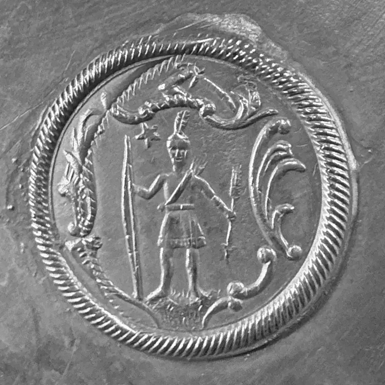
- Partnership: Roswell and Roswell Gleason, in 1850-1871, in Dorchester MA. As R. GLEASON & SONS, manufacturers of Britannia and silverplate goods. 12
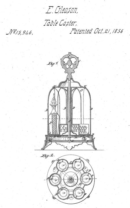
- Patent: 15,946, on 21 Oct 1856. EDWARD GLEASON, OF DORCHESTER, MASSACHUSETTS.
BOTTLE-CASTER.
Specification of Letters Patent No. 15,946, dated October 21, 1856.
To all whom it may concern: Be it known that I, EDWARD GLEASON, of Dorchester, in the county of Norfolk and State of Massachusetts, have invented a new and useful Improvement on Revolving Bottle-Casters; and I do hereby declare that the following is a full, clear, and exact description of the same, reference being had to the annexed drawings, making a part of this specification, in which—
Figure 1, is a vertical section of my improvement, (x), (x) Fig. 2, showing the plane of section. Fig. 2, is a horizontal section of ditto (y) (y) Fig. 1, showing the plane of section.
Similar letters of reference indicate corresponding parts in the two figures.
To enable others skilled in the art to fully understand and construct my invention, I will proceed to describe it.
A, represents the base of the caster, over which a plate B, is placed, which plate forms the bottom of the body C, of the caster.
The body C, may be of any pattern or form, and it is provided with doors D, fitted to its sides, any proper number being employed. The upper ends of the doors D. have each a pivot (a) attached to them, which pivots are fitted in the upper plate E, of the body C. The doors are of semi-spherical or niched form, as clearly shown in Fig. 2, and have bottoms (b) on which the bottles F, rest, the bottles fitting within the concaves of the doors. The doors of course are fitted in recesses in the body of the caster.
To the under side of the bottom of each door there is attached a rod (c) and on each rod there is placed a pinion G. The pinions G, gear into a spur wheel H, which is attached to the lower end of a rod I, which passes vertically through the center of the body C, and through the center of the bottom of the base A, the rod I, having a nut (d) on its lower end, and a handle J, on its upper end.
To the under side of the plate B, there are attached rods (e) three or more, which have rollers (f) fitted in their lower ends, the, rollers resting upon the bottom of the base A, as clearly shown in Fig. 1, and working in an annular groove (g) in the base.
By turning the rod I, by means of the handle J, the doors D, will be turned in consequence of the wheel H, and pinions G, and the bottles F, may consequently be turned outward and be upon the outer side of the body C, ready for use or be turned within the body C, when not intended to be used.
When the doors D, are either opened or closed to their fullest extent, the body C, will rotate as the pinions G, will not turn, and the plate B, and body C, are then connected with the shaft I.
The above invention is simple and useful as the bottles when within the body C, are protected from dust, and the body of the caster may be rotated equally as well as those in common use. Now, in this arrangement, it will be observed that there is an essential difference between it and a previous arrangement wherein the doors containing the bottles were pivoted at their one edge and the bottles arranged intermediate of the pivot and lip or
outer edge of the door and the doors being swung backward by the turning of the center handle, when required to expose the bottles which were thus made to travel through the path of a circle on one side only as it were of the pivot, thereby subjecting the bottles to an increased travel and exposing them, on suddenly or abruptly opening the doors, by the centrifugal effect produced, to being jerked put of their seats or the stoppers out of the bottles and producing a disagreeable clatter, besides which the doors in opening occupied more space than the caster proper in its closed condition did which subjected the doors or bottles to injury or breakage on a crowded table. These and other objections it is obvious are removed by the construction arrangement and operation herein described of the doors D carrying or having the bottles F arranged on or over their pivoted centers.
I do not claim any of the devices separately considered, nor yet, of itself, a caster provided with doors to inclose the bottles and opened to expose them by the turning of the center handle or rod of the caster; but
I do claim as new and useful in revolving door casters—
1. The arrangement of the bottles F centrally or thereabout on or over the pivots of the niched or semi-cylindrical doors D when the latter are arranged for operation in relation to the body of the caster by the central rod or handle as described.
2. I also claim so gearing and connecting the revolving body C of the caster with its separately turning doors D and arranging the same with its stationary base A, that upon continuing to turn the central rod I, after the doors have been opened or closed, in the same direction which was required to open and close them, the whole body of the caster is made freely to turn on its base A with the doors in the conditions they were set by said turning of the central rod I or handle as set forth.
Edward Gleason.
Witnesses:
A. J. Vose
T. V. Gleason
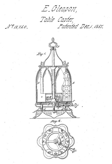
- He was issued patent number 18,740 on 1 Dec 1857
EDWARD GLEASON, OF DORCHESTER, MASSACHUSETTS.
REVOLVING BOTTLE-CASTER.
Specification of Letters Patent No. 18,740, dated December 1, 1857.
To all whom it may concern:
Be it known that I, EDWARD GLEASON, of Dorchester, in the county of Norfolk and State of Massachusetts, have invented a new and useful Improvement in Revolving Bot tle-Casters ; and I do hereby declare that the following is a full, clear, and exact descrip tion of the same, reference being had to the accompanying drawings, making a part of this specification, in which—
Figure 1 is a vertical central section of my improvement. Fig. 2 is an inverted plan of the same; the base of the imple ment being removed.
Similar letters of reference indicate like parts in the two figures.
This invention relates to an improvement on a revolving bottle caster formerly pat ented by me; the Letters-Patent bearing date Oct. 21st, 1856.
The invention consists in having the de vice by which the doors of the caster are turned, arranged separately so as to have no connection whatever with the body of the caster, so far as the rotation of said body is concerned.
The object of the invention is to render the movement of the caster and doors inde pendent of each other, so that either may be directly moved or turned as desired, without at all depending upon the move ment of the other.
To enable those skilled in the art to fully understand and construct my invention, I will proceed to describe it.
A, Fig. 1, represents the base of the caster, which may be of any proper form; and B represents the body of the caster, the bottom of which has rollers (a) attached to it, which rollers fit and work in an annular groove (b) in the base.
C is a rod which is placed centrally with in the body B; the upper end of said rod having a handle or knob D, attached, and the lower end having a rod (e) attached, which rod passes through the center of the base A, and has a nut (d) upon its lower end; said nut securing the body and base together. The body B is allowed to rotate freely on the base A.
E, represent doors which are of niche form; each being pivoted centrally to the body B, and forming its sides; any proper number of doors being used. Each door has a socket (e) at its lower end, to receive the bottles and retain them within the niches. The lower pivots (g) of the doors E pass through the bottom A1 of the body of the caster, and have each a pinion (A) placed on them. These pinions gear into a wheel F, which is placed loosely on the rod (c); and said wheel F has a segment rack (d1) formed on it, near its center, into which rack a pinion (e1) gears, said pinion being on the inner end of a rod or arbor (f) which passes through the side of the bottom A1, and has a knob (i) on its outer end.
From the above description of parts, it will be seen that the body B, of the caster may be turned independently of the doors; and the doors, by turning the rod or arbor (f) may be turned without affecting the body B.
In the caster formerly patented by me, the movements of the body and the doors were connected; both being actuated by turning a single rod or handle. This ar rangement, although convenient when per sons are accustomed to them, is very embar rassing at first, as the doors must be either fully opened or closed before the body can be turned and consequently it frequently occurs that several essays are made before the desired movement is obtained. But by the improvement herein described, this objection is obviated.
I do not claim, separately and broadly, the revolving doors E, nor the revolving body B. But
Having thus described my invention, what I claim as new, and desire to secure by Letters Patent, is:—
The combination of the pinions (K) (h) (h) (each moving a caster door and cruet) and the wheel F with the pinion (e') of the i rod or arbor (f). the said pinion (e') gearing into a segment rack (d') in the wheel F as set forth, so that when this combination is actuated through the knob (i), the caster cruets and doors to which they are: attached, may be rotated independently of the rotation of the body B of the caster.
Edward Gleason
Witnesses:
John P. Vose
Andrew J. Vose
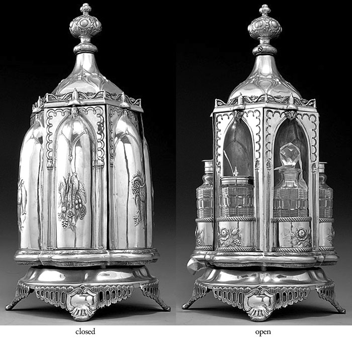
- Example: Revolving castor frame, circa 1857, in Private Collection. H: 17"
d: 6 1/2"
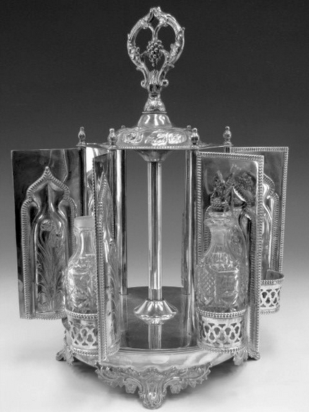
- Example: Revolving castor frame, circa 1857, in Private Collection. H: 16 1/2"
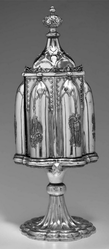
- Example: Revolving castor frame, circa 1860, in Museum of Fine Arts, Boston. H: 22"
dia: 8 3/4"
|


