Roswell Gleason
- Born: 25 Sep 1826, Dorchester MA
- Died: 22 Jul 1866, Dorchester MA
General notes:
Silverplater
Events in his life were:
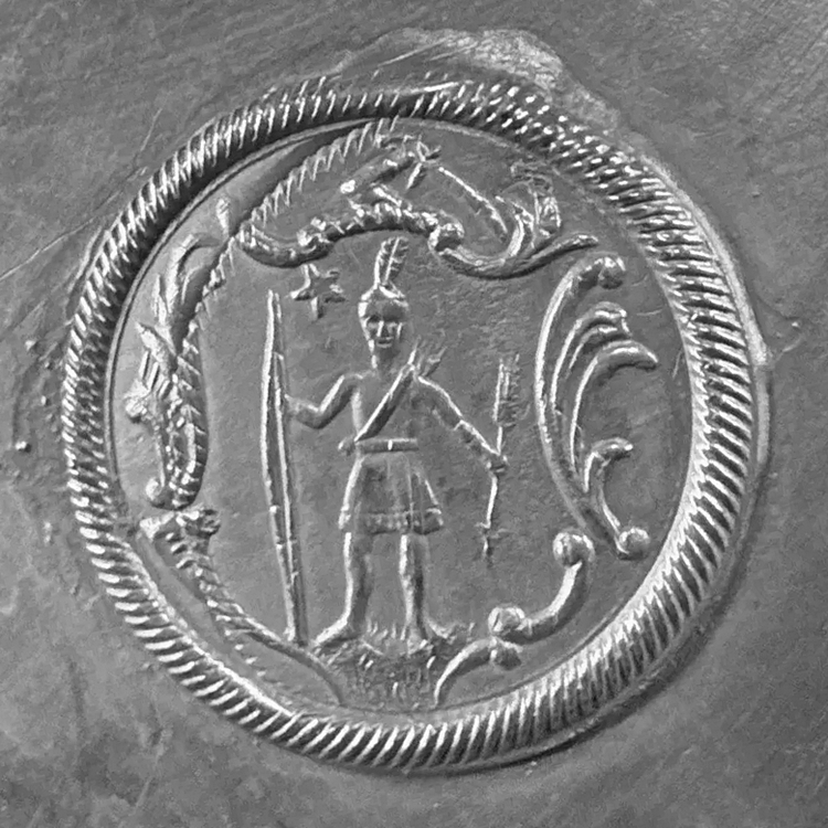
- Partnership: Roswell and Edward Gleason, in 1850-1871, in Dorchester MA. As R. GLEASON & SONS, manufacturers of Britannia and silverplate goods. 12
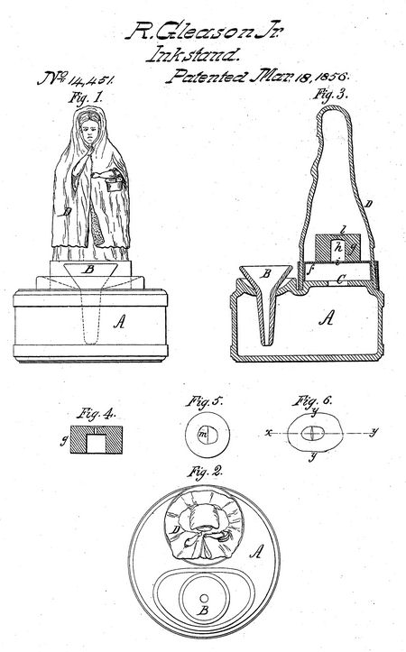
- He was issued patent number 14,451 on 18 Mar 1856
R. GLEASON, JR., OF DORCHESTER, MASSACHUSETTS.
INKSTAND
Specification of Letters Patent No. 14,451, dated March 18, 1856.
To all whom it may concern: Be it known that I, R. GLEASON, Jr., of Dorchester, in the county of Norfolk and State of Massachusetts, have invented certain new and useful Improvements in Inkstands, of which the following is a full, clear, and exact description, reference being had to the annexed drawings, making part of this specification, in which—
Figure 1 is a view of an inkstand with my improvements attached; Fig. 2, a plan; Fig. 3, a vertical section through the same; Figs. 4, 5, and 6, details which will be referred to hereafter.
My invention is applied to that species of inkstand known as fountain inkstands, in which the ink is forced up into the cup by compressing the air within the stand, and my invention consists in attaching to an opening in the inkstand a hollow image, globe, or other article, which when subjected to pressure shall compress the air within the stand and force up the ink as required, the air being prevented from leaving the interior of the stand by a suitable valve or by containing the pressure upon the hollow image or globe.
To enable others skilled in the art to make and use my invention, I will proceed to describe the manner in which I have carried it out.
In the accompanying drawings A, is the inkstand; B, the funnel or cup into which the ink is to be forced; D, a hollow image of india rubber attached with an air tight joint to the inkstand over an opening C, in its top. If now the image be subjected to pressure in any way so as to drive the air which it contains into the inkstand, the ink will be forced into the cap B, as required. There are various methods by which the air may be prevented from returning to the image until desired, for instance the image may be bent over to one side and confined in the position by a hook or otherwise, until it is desired to return the ink into the inkstand. The method however which I prefer for the purpose is by the use of a valve of peculiar construction which I will proceed to describe.
F, is a metal cap secured to the image D and to the top of the inkstand with an air tight joint.
I, is a hole in the center of this cap over which is secured the block of india rubber g; this block has a hole A, of the size represented in the drawings, passing nearly through it, the portion l, being perforated with a narrow slit m, (Fig. 5,) which closes of itself air tight, but which may be opened as in Figs. 4, and 6, by pressure at the points y, y.
Operation: When it is desired to force the ink from the stand into the cup, B, pressure is applied by the hand to the body of the image above the valve, and a portion of air is then forced into the inkstand, where it is retained by the valve in the block g.
When it is requested to drop the ink again into the inkstand, pressure is applied to the image lower down so as to compress the valve as in Figs. 4 and 6, without diminishing the size of the image, when the air is allowed to return from the stand to the interior of the image, and the ink again descends into the inkstand.
What I claim as my invention and desire to secure by Letters Patent is—
The use of the hollow elastic body operating in the manner set forth, in combination with the peculiar valve employed for the purpose of retaining the ink within the cup as set forth.
R. Gleason, Jr.
Witnesses:
Thos. E. Roach
T. E. Teschemacher
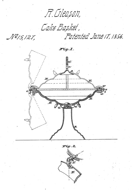
- He was issued patent number 15,127 on 17 Jun 1856
R. GLEASON, JR., OF DORCHESTER, MASSACHUSETTS.
SILVER-PLATE CAKE AND FRUIT BASKET.
Specification of Letters Patent No. 15,127, dated June 17, 1856.
To all whom, it may concern:
Be it known that I, R. Gleason, Jr., of Dorchester, in the county of Norfolk and State of Massachusetts, have invented a new and useful Improvement in Cake and Fruit Baskets; and I do hereby declare that the following is a full, clear, and exact description of the same, reference being had to the annexed drawings, making a part of this specification, in which—
Figure 1, is a vertical section of my improvement, the plane of section being through the center. Fig. 2, is a detached proper view of one of the swivel joint hinges by which the lids are connected to the basket.
My invention consists in having two lids or covers connected to the basket by swivel joint hinges as will be presently shown, whereby the lids or cover may be fitted or adjusted over the top of the basket or turned down and secured underneath the basket.
This invention is designed for plated or metallic cake and fruit baskets.
To enable those skilled in the art to fully understand and construct my invention, I will proceed to describe it.
A, represents the body of the cake or fruit basket and B, represents the base which supports the body A.
C, is the handle of the basket having pendent arms (a), attached to it at its center said arms having a horizontal circular plate D, attached to them, the plate being over the center of the body A.
To the upper edge of the body A, there are attached two lids or covers E, E, the lids or covers being at opposite sides of the body A, and connected to it by swivel joint hinges F, F. These hinges are formed by having pintles (b), passing through sockets (c), attached to the edges of the body A.
The pintles are secured in the sockets by nuts or heads on their inner ends the pintles being allowed to turn freely in the sockets. The outer ends of the pintles have forked arms (d), connected to them one to each by pins (e), which pass through the prongs of the forks and through the outer ends of the pintles. The lids or covers E, E, are of course made to conform to the shape of the body A. In the upper end of the base B, there are fitted two spring catches G, G, one for each lid or cover E. When the lids or covers are over the body A, of the basket their upper ends rest upon the edge of the plate D, as shown in red Fig. 1. When the lids or covers are not required to be over the basket they are raised in a vertical position as shown in red dotted lines Fig. 1, then turned vertically downward as shown in black dotted lines, and then turned upward underneath the body A, and are secured in that position by the catches G, G.
The above invention is extremely simple and enables the basket to be converted into an open or covered one in a moment of time.
Having thus described my invention what I claim as new and desire to secure by Letters Patent is: .
Attaching the two lids or covers E, E, to the box A, of the basket by the swivel joint hinges F, F, constructed as shown; the lids or covers corresponding in form to that of the body A, whereby the lids or covers may be placed over the body A, or turned downward and secured by the catches G, G, underneath the body substantially as described.
R. Gleason, Jr.
Witnesses:
Andrew J. Vose
Edward Gleason
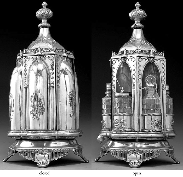
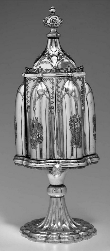
- Example: Revolving castor frame, circa 1857, in Private Collection. H: 17"
d: 6 1/2"
- Example: Revolving castor frame, circa 1857, in Museum of Fine Arts, Boston. H: 22"
dia: 8 3/4"
- He was issued patent number 23,218 on 8 Mar 1859
R. GLEASON, JR., OF DORCHESTER, MASSACHUSETTS, ASSIGNOR TO R. GLEASON & SONS, OF SAME PLACE.
TABLE-CASTER.
Specification forming part of Letters Patent No. 23,218, dated March 8, 1859; Reissued December 27, 1859, No. 871.
To all whom it may concern:
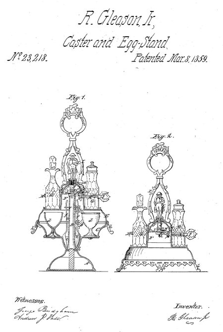
Be it known that I, R. GLEASON, Jr., of Dorchester, in the county of Norfolk and State of Massachusetts, have invented a new and useful Article of Manufacture for the Table, the same being a Combination of Caster, Egg-Stand, and Bell; and I do hereby declare that the following is a full, clear, and exact description of the same, reference being had to the annexed drawings, making a part of this specification, in which—
Figure 1, is a vertical central section of my invention complete. Fig. 2, a detached vertical central section of the caster and bell.
Similar letters of reference indicate corresponding parts in the two figures. This invention consists in combining an egg-stand, caster and bell, as hereinafter fully shown and described, whereby either article may be used separately when desired, and the egg stand when not required for use, made to serve as a revolving support for the caster and bell, the several articles forming a very ornamental affair, and a much more economical one than if the several pieces were made separately.
To enable those skilled in the art to fully understand and construct my invention I will proceed to describe it.
A, Fig. 1, represents a base in which a vertical rod B, is placed centrally, and C, is a circular basin or dish which is provided with a central tube a, through which the rod B, passes, the tube a, extending nearly to the top of the rod B, as shown clearly in Fig. 1. The basin or dish C, is allowed to rotate freely on the rod B, the bottom of the basin or dish resting or bearing on the top 6, of the base A, a sufficient bearing surface being allowed for such purpose.
Within the disk or basin C, a series of vertical rods c, are secured on which eggcups d, are placed, said rods keeping the cups in proper position, and at the center of the dish or basin, encompassing the base of the tube a, an annular chamber e, is formed to receive the bowls of spoons f, the upper ends of which are secured in a circular rack g, attached to the upper part of the tube a. The above parts which are all shown in Fig. 1, constitute a revolving egg-stand, and if used separately a handle D, may be screwed into the upper end of the rod B, as shown in red Fig. 1.
E, is a circular inverted dish having a cylindrical chamber F, at its center, said chamber being considerably smaller in diameter than the dish E, so as to afford space all around it to hold cruets G, which are placed in annular holders H, secured to the upper part of the chamber F.
The bottom of the dish E is provided with feet h, and to the upper part of the chamber F, a handle I, is attached, as shown clearly in Fig. 2.
Within the upper part of the chamber F, a bell J, is secured, the part of the chamber which immediately encompasses said bell, being perforated as shown at i. The bell is secured in proper position by a tube j, through which a screw rod k, passes. On the tube j, a hammer rod l, is secured by a pivot m, and n, is a spring which is connected with the hammer rod as shown at o. K, is a rod which passes horizontally through the chamber F, and has a wiper p, on its inner end within the chamber F, the outer end of said rod having a handle q, placed on it.
The bell J, it will be seen is sounded by turning the rod K, the wiper p, of which in connection with the spring n, actuates the hammer rod l.
The parts which are shown in Fig. 2, and latterly described constitute the caster and bell and may be used detached from the egg-stand if desired. When used in connection with the egg-stand, the handle D, is detached from the upper end of the rod B, and the caster placed over the egg-stand, the screw rod k, being screwed into the upper end of the rod B, by means of any suitable handle L.
The inverted dish or basin E, of the caster serves as a cover for the egg-stand con- cealing it and its appurtenances from view and the egg-stand serves as a revolving base for the caster, the whole forming a very useful and unique article for the table, and one that may be constructed much cheaper than if the several parts were made separately, for one device is made in a measure to serve the other, for instance, a caster whether stationary or rotary should, if proportion is at all considered, have a base of some considerable height and the same may be said of an egg-stand.
By my invention one base is used for both the egg-stand, and caster, and as the former comparatively is but rarely used it serves as a superior revolving base for the caster which is almost invariably used. Many therefore who would not go to the expense of providing themselves with an egg-stand, would purchase the several parts combined, at a slight advance on a caster alone.
I do not claim separately any of the parts herein shown and described, when seperately considered; but, I desire to secure by Letters Patent and claim-—
As a new and useful article of manufacture a caster, egg-stand and table bell, arranged and combined as herein shown and described.
R. Gleason, Jr.
Witnesses:
Andrew J. Vose
Robert Vose
|


