Franklin Dana Hall
- Born: 20 Sep 1811, Wallingford CT
- Marriage (1): Elizabeth Kingsley Tiffany on 21 Sep 1835
- Died: 13 Jan 1857, Philadelphia PA
General notes:
Pewtersmith
Events in his life were:


- Partnership: Henry Sherman Boardman, circa 1846-1857, in Philadelphia PA. As HALL, BOARDMAN & Co. By 1848, the firm was renamed HALL & BOARDMAN, listed in the 1850 city directory at 104 North 3rd Street.
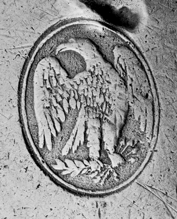
- He appeared on the census in 1850 in Philadelphia PA. Listed as a britannia manufacturer.

- Advertised: Atlas of America, in 1856. For HALL & BOARDMAN
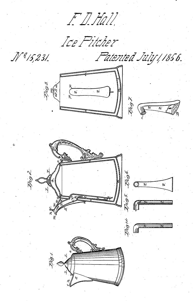
- He was issued patent number 15,331 on 1 Jul 1856
FRANKLIN D. HALL, OF PHILADELPHIA, PENNSYLVANIA.
Refrigerating-Pitcher.
Specification of Letters Patent No. 15,331, dated July 1, 1856.
To all whom it may concern:
Be it known that I, Franklin D. Hall, of the city of Philadelphia, in the State of Pennsylvania, have invented a new and useful improvement in ice-pitchers to be used for the purpose of containing and preserving water and other liquids cool and convenient for drinking in warm temperatures by means of ice therein, of which the following is a full and exact description, reference being made to the annexed drawings, making a part of this specification, in which—
Fig. 1, represents an external view of my pitcher.
Fig. 2, represents a vertical sectional view of my pitcher (constructed with double walls lid and bottom) bisected by a vertical plane passing through the middle of the pitcher, the spout S, the small hinged cover c, and the tube or pipe t, t, t', attached to the inner wall, and passing upward through the double walls at p, p, and through the interior of the spout, terminating at the mouth m. The small cover c, is seen in this figure, raised from the mouth of the spout on its hinge at h. The spaces a, a, a, a, a, a' a' are between the double walls, and contain air
Fig. 3, represents an interior view of a part of the pitcher, and a front view of that portion of the tube or pipe t, t, which is attached to the interior wall, and the place p, p, where it binds outward and passes through the double walls, from whence it extends upward and forward through the spout S, which incloses it, terminating and uniting with the spout near its mouth m. The upper wall, or fixed cover of the spout w, w, inclosing a portion of the tube is seen in this figure projected from the side of the pitcher.
Fig. 4, is an external view of the tube t, t, the upper part bent to pass through the walls.
Fig. 5, is a sectional view of the same.
Fig. 6, is a view of that side of the flattened tube or pipe which is to be attached to the interior wall of the pitcher.
Fig. 7, represents the tube or pipe flattened and widened toward the base, the upper end bent to pass through the walls, as the same appears when detached from the side of the pitcher. A part of one side of the tube is removed, showing the same closed at the bottom by a plate which forms its base B. This base is perforated by a number of small holes to allow the free passage of the liquid, the direction of the flow of which is indicated in this, as in some of the other figures, by arrows.
I make my pitcher of metal, usually brittannia, with double walls, double bottom and double lid, leaving the intermediate spaces a, a, a, a, filled with air, as in Fig. 2. The lid L, L, is made so as to sit into and on the top of the pitcher fitting very closely, the outer edge projecting and resting upon the top of the pitcher at o, o. I then make and attach to the outside of the pitcher the spout S. I cover over this spout across the top with a plate w, w, Fig. 3, attached to the side of the pitcher and upper edge of the spout, leaving a small opening at the upper and outer extremity large enough to allow the free passage of the liquid in pouring. This opening m, Fig. 2, forms the mouth of the spout; over the mouth m, is fitted the small movable cover, c, Figs. 2, and 3, which is hinged to the outer edge of the larger fixed cover of the spout at A. This small movable cover c, is seen closed in Fig. 1, and raised in Fig. 2. To the interior wall of the pitcher under and opposite the spout I attach a tube or conduit pipe t, t, of sufficient capacity to allow the free passage of a liquid. This tube I flatten on the inside of the pitcher and widen it somewhat toward its base (Figs. 6 and 7). It reaches downward almost to the bottom of the inside of the pitcher, and upward along the interior wall to about midway between the upper and lower extremities of the spout. It is then bent and made to pass through the double wall, at p, p, from whence it is further extended upward and forward through the space inclosed by the spout S, to its mouth m, at or near which the exterior surface of the upper end of the tube joins and is soldered to the edges of the mouth m, Fig. 2. Thus the exterior surface of that part of the tube t' which passes through the spout, with the surrounding wall, and fixed cover w, w, form a double-walled spout, with the intermediate air spaces a', a'. The lower end of the tube is closed up by a transverse plate B, Fig. 7, perforated with a sufficient number of small holes to pass the liquid but effectually excluding the passage of pieces of ice or other solid substances.
In the act of pouring the pressure of the liquid lifts the cover c, which, upon the vessel being restored to its upright position, falls again to its place.
My improvement consists in the use and arrangement of the tube or conduit pipe attached to the inside of the double-walled pitcher and extending the same up through the spout in the manner described, by means of which the liquid is drawn from the bottom of the vessel through continuous double casings to the very place of its exit. The pitcher when filled remains closed, without any external air being admitted other than enough to supply the vacuum made by pouring until the contents are exhausted or very nearly so. When standing filled, the water is preserved cool by being entirely inclosed in double casings, excepting the surface of the small cover at the mouth, thus possessing very important advantages as a useful, convenient and economical ice pitcher.
I am aware that double walls and casings containing intermediate strata of air, have long been used in pitchers and other articles of household economy as a means of intercepting and retaining heat. I am also aware that hinged covers to protect the mouth or spout of vessels from which fluids are to be poured, as pitchers, molasses cups and such like articles, have long been in use. These contrivances I therefore entirely disclaim.
What I do claim, and desire to secure by Letters Patent is—
The arrangement of the tube or conduit pipe, and the spout with which it is connected in the manner and for the purposes hereinbefore described.
Franklin D. Hall.
Witnesses:
I. A. Spencer
Charles D. Freeman
Franklin married Elizabeth Kingsley Tiffany, daughter of Jonathan Tiffany and Experience Chamberlain, on 21 Sep 1835. (Elizabeth Kingsley Tiffany was born on 15 Jul 1815 in Sturbridge MA and died on 11 Nov 1862 in Philadelphia PA.)
|


