Isaac Madison Miller
- Born: 1837, Westfield NJ
- Died: 11 Sep 1906
General notes:
Jeweler
Events in his life were:
- Partnership: James Wesley Miller, after 1854, in Newark NJ. As MILLER BROTHERS, manufacturing jewelers with a factory at 47-51 Franklin Street.
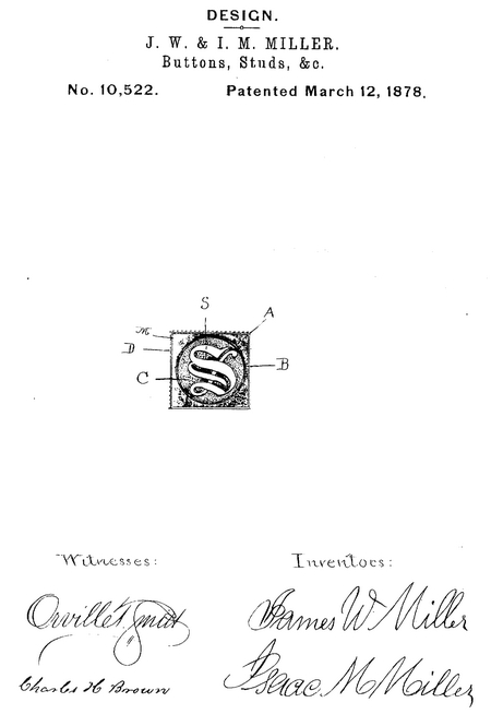
- Patent: 10.522, on 12 Mar 1878. JAMES W. MILLER AND ISAAC M. MILLER, OF NEWARK, NEW JERSEY.
DESIGN FOR BUTTONS, STUDS, &c.
Specification forming part of Design No. 10.522, dated March 12, 1878; application filed February 18, 1878.
To all whom it may concern:
Be it known that we, James W. Miller and Isaac M. Miller, of Newark, county of Essex, State of New Jersey, have originated a useful Design for Buttons, Studs, Lockets, Medallions, Pins, Ear-Rings, and Bracelets, of which the following is a full, clear, and exact description, reference being had to the accompanying photographic illustration, making part of this specification.
A reference to our Design Patent No. 10,100, dated July 17, 1877, will show that this is an amplification of, and an amendment to, it.
A represents the body or base of the button, stud, locket, medallions, pins, ear-rings, and bracelets, square in shape, with its center cut out in a circular form. B represents a raised rim around the circular form in the center of the base A. C represents a depressed center, and is accomplished in the following manner: It is first made in the same form as, and to fit in, the reverse side of the base A, to which it is riveted, thus showing on the face of the design a depressed center.
D represents a shotted edge or border, placed around the sides, and at the lowest edge of the base A, while just above the shotted edge D is placed a line of twisted wire, M. S represents an "Old English" letter, mounted on the depressed center C, and may be any letter of the alphabet.
Our claim is—
A design for a button, stud, locket, medallion, pin, ear-rings, and bracelets, consisting of the square-shaped base A, with the raised rim B, the depressed center C, mounted with any letter of the "Old English" alphabet, one of which is represented at S, the shotted edge D, and twisted wire M, all in combination, and in shape and position substantially as described, and shown in the accompanying photographic illustration.
James W. Miller
Isaac M. Miller
Witnesses:
Orville T. Smith
C. W. Nassau
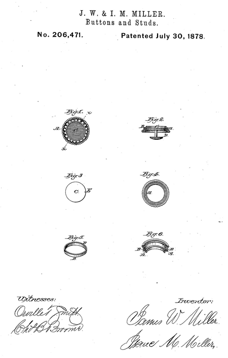
- He was issued patent number 206,471 on 30 Jul 1878
JAMES W. MILLER, OF NEWARK, AND ISAAC M. MILLER, OF ORANGE, NEW JERSEY.
IMPROVEMENT IN BUTTONS AND STUDS.
Specification forming part of Letters Patent No. 206,471, dated July 30, 1878; application filed May 10, 1878.
To all whom it may concern:
Be it known that we, James W. Miller, of Newark, Essex county, and Isaac M. Miller, of Orange, Essex county, State of New Jersey, have invented new and useful Improvements in the Manufacturing of Sleeve-Buttons and Studs; and we hereby declare that the following is a true and exact description of our invention, which will enable others to make and use the same, reference being had to the accompanying drawings, forming a part of this specification, and to the letters and figures of reference marked thereon.
The object of our invention is to construct a button in such a manner as to facilitate the putting together of the several pieces of which the button or stud is composed, the details of which will be hereinafter fully set forth.
Referring to the drawings, Figure I is a face view of an improved sleeve-button, representing the parts assembled. Fig. II is a vertical sectional view. Fig. III is a top view of the center plate. Fig. IV is an inverted view of the outer rim or border. Fig. V is a view of the inner rim or border to the center plate. Fig. VI is a sectional inverted view of the outer and inner rims combined.
A represents the outer rim or border. B represents the inner rim or border. 0 represents the center plate, which is connected by a stem to a lower disk. D represents the edge of the inner rim, B, which, when turned over, secures the center plate, C. E represents the edge of the center plate, C, over which is turned the edge D of the inner rim, B.
The outer rim or border, A, Fig. IV, and inner rim or border, B, Fig. V, are soldered together, as shown in Figs. II and VI. The center plate, C, is then placed in position. (See Fig. II.) Then, with proper tools, the edge D of the inner rim, B, is turned over the edge E of the center plate 0, thus firmly securing all the parts together.
By this arrangement the center plate, C, may be made of inferior metal to the Etruscan-colored gold rims or borders A and B, thereby increasing the strength and decreasing the cost of manufacturing the article.
We claim—
A button consisting of the annular part A, to which is secured an inner rim or flange, B, in combination with a stud having a disk secured to each end thereof, the inner rim or flange being adapted to be upset over the upper of the two disks, to unite the parts which form the button, substantially as set forth.
James W. Miller
Isaac M. Miller
Witnesses:
Lucius W. How
Orville T. Smith
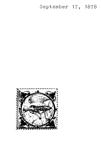
- Patent: 10,831, on 17 Sep 1878. JAMES W. MILLER, OF NEWARK, AND ISAAC M. MILLER, OF ORANGE, N. J.
DESIGN FOR BUTTONS, &c.
Specification forming part of Design No.10,831, dated September 17, 1878 ; application filed June 15, 1878.
To all whom it may concern:
Be it known that we, James W. Miller, of Newark, Essex county, and Isaac M. Miller, of Orange, Essex county, State of New Jersey, have invented a new and useful Design for Buttons, Studs, Lockets, Medallions, Pins, Ear-Rings, and Bracelets, of which the following is a full, clear, and exact description, reference being had to the accompanying photographic illustrations, making part of this specification.
A represents the face of a button as described. B represents a bird on the branches of a bush or tree, facing to the left, and with drooping tail and wings raised as if in the act of flying downward from the branch, b b b
represent a portion of the branches of the bush or tree, c c c c represent a portion of the fruit and leaves on the branches, the -whole bounded by a circle surrounded by scroll-work inclosed in a square corded or beaded border. We claim—
The design for sleeve-buttons and other jewelry, composed of the bird B, branches b b b, and fruit and leaves c c c c within a circle surrounded by a suitable border, substantially as described and shown.
James W. Miller
Isaac M. Miller
Witnesses:
Lucius W. How
Orville T. Smith
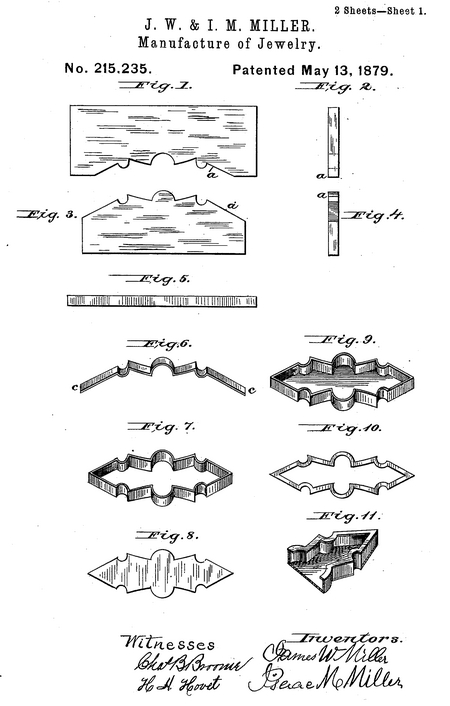
- He was issued patent number 215,235 on 13 May 1879
JAMES W. MILLER, OF NEWARK, AND ISAAC M. MILLER, OF ORANGE, N. J.
IMPROVEMENT IN THE MANUFACTURE OF JEWELRY.
Specification forming part of Letters Patent No. 215,235, dated May 13, 1879; application filed February 13, 1879.
To all whom it may concern: Be it known that we, James W. Miller, of the city of Newark, and Isaac M. Miller, of Orange, both in Essex county, State of New Jersey, have invented a new and useful Improvement in the art of Manufacturing Jewelry ; and we hereby declare that the following description is such as will enable-others skilled in the art to make and use the same, reference being had to the accompanying drawings, forming a part of this specification, and to the letters and figures of reference marked thereon.
The object of our invention is to beautify, strengthen, and cheapen the manufacture of jewelry.
To more clearly show our new process, we will first describe the old method or process usually employed, then our new process.
Figure I represents an old upper shaper. Fig. II represents a sectional view of an old upper shaper. Fig. III represents an old lower shaper. Fig. IV represents a sectional view of an old lower shaper.
a a represent the working edges of the old lower and upper shapers.
Fig. V represents a strip or piece of gold or other metal previous to being placed between the edges a a of the upper and lower shapers. Fig. VI represents the strip or piece of gold or other metal, as in Fig. V, after being bent into shape by the edges a a of the upper and lower old shapers. (See Figs. I and IV.) Fig. VII represents two bent strips, as in Fig. VI, soldered together at their ends c c, thus forming the skeleton of an article. Fig. VIII represents a face view of a top of an article previous to soldering to the skeleton or border. Fig. IX represents an inverted view of the skeleton with top (see Fig. VIII) soldered on, thus showing the thin edge of articles made previous to our new invention. Fig. X represents a cut or pierced rim previous to its being soldered to the thin edge of the skeleton. (See Fig. IX.) Fig. XI represents a sectional view of a finished article.
Owing to the expense in cutting or piercing out a rim to fit the different outlines of the desired article, manufacturers have generally left the edge on the back of an article with its thin edge, thus making the article necessarily weak.
By our new invention we obviate the extra expense of making extra tools as required by the old way and the time and labor taken to solder the rim on when pierced out.
We will now describe our new invention.
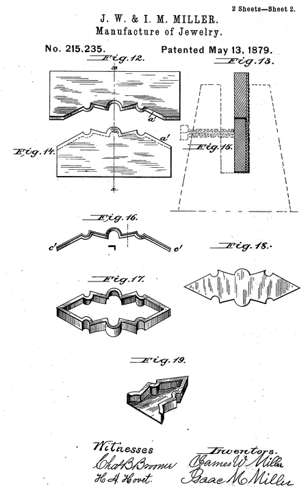
Fig. XII represents a view of our new upper shaper. Fig. XIII represents a sectional view of our new upper shaper, taken on line x x, Fig. XII. Fig. XIV represents a view of our new lower shaper. Fig. XV represents a sectional view of our new lower shaper, taken on line x x, Fig. XIV.
a' a' represent the working edges of our new upper and lower shapers, which are made to correspond in form and shape to the desired article, and are used in bending and compressing or swaging pieces of gold or other metal, as shown in Fig. V, into preparatory forms, as shown in Fig. XVI. These edges are arranged in the shape of an L, so that when brought together the flange part of the L edge of the upper shaper will press the edge of the strip of metal into the flange part of the L edge of the lower shaper, thus producing a rim at once turned at right angle to the strip of metal with which the border or skeleton of an article is to be made, producing the same in a cheap and easy manner by compression.
By this method the expensive system heretofore in use and described in this specification of cutting or piercing out a rim, and soldering the same upon the article, is avoided, and manufacture thereby cheapened.
Fig. XVI represents the strip of gold or other metal, as shown in Fig. V, bent and compressed into form, but with rim provided by our new process. Fig. XVII represents two bent and compressed strips of gold or other metal, as shown in Fig. XVI, soldered together at the ends c' c', thus forming the skeleton or border and rim of an article. Fig. XVIII represents a face view of a top of an article previous to soldering to the skeleton or border. Fig. XIX represents a sectional view of a finished article.
We claim—
The hereinbefore described improvement in the art of manufacturing jewelry, which consists in bending strips of metal into the forms required for one side of the desired article by means of suitable dies, and simultaneously by means of the dies forming the rear flange or rim, as and for the purpose described.
James W. Miller
Isaac M. Miller
Witnesses:
Orville T. Smith
Thos. B. Clifford
- Patent: 12,482, on 20 Sep 1881. JAMES W. MILLER, OF NEWARK, ASSIGNOR OF ONE-HALF TO ISAAC M. MILLER, OF EAST ORANGE, NEW JERSEY.
DESIGN FOR A SLEEVE-BUTTON.
SPECIFICATION forming' part of Design No. 12,482, dated September 20, 1881.
To all whom it may concern :
Be it known that I, James W. Miller, of the city of Newark, county of Essex, and State of New Jersey, have invented and produced a new and original Design for Sleeve-Buttons, Lockets, and Similar Articles of Jewelry, which design is fully set forth in the following specification.
The button or other article upon which the design is to be used may be of any ordinary or suitable material, such as gold, silver, celluloid, bard rubber, and the like. Upon the face of the button or other article is an initial letter or letters, which are generally formed separately and applied to the face of the article; but they may be produced by embossing, so that they shall stand out in rilievo, or they may be countersunk, or the outlines determined by mere engraving. The letters themselves may be of any pattern, plain or ornamental, simple initial letters, or several letters interlaced mono-graphically, or placed side by side, as may be desired. Within the contour or outline of the letter or letters are formed, by engraving, etching, or otherwise, landscapes or water views, and these views may be varied indefinitely or modified as to detail, as will be hereinafter more fully set forth.
The said design will now be described in connection with the accompanying drawings, which form a part of this specification, and in which—
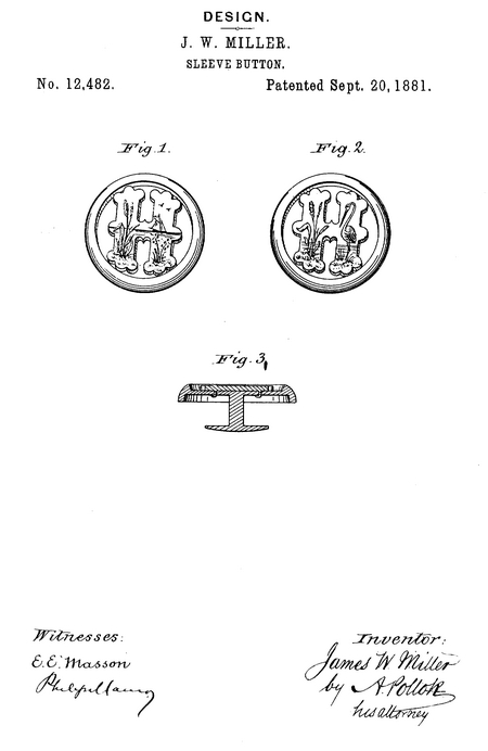
Figures 1 aud 2 are top views of a sleeve-button or similar article, illustrating the design upon the face thereof; and Fig. 3, a sectional view, showing the formation of the initial letter in rilievo.
On the face of the letter shown in Fig. L is a view representing earth in the foreground, with water in the distance and sky overhead. By using different-colored metals, as gold and silver, or the various alloys of gold, for the different portions of the field, a more striking effect may be produced. The representation of a plant is in the foreground of the picture. This may be replaced by the figure of a bird, as in Fig. 2, or other appropriate object, and the scene may be made more realistic by the representation of a sail upon the water in the distance and of birds tlyiug overhead, as shown in the figure.
Fig. 2 represents a somewhat different scene, and serves to show how the design may be varied without departing from the spirit of the invention. The landscape or water view, as well as the various details thereof, may be further varied as the faucy may suggest or to suit the outline of the particular initial letter or letters upon which they are to be produced.
The buttons or other articles upon which the design is used may be of precious metals or of other substances from which such articles are commonly made. Where the precious metals are employed the effects of earth, sky, and water may be produced, as already explained, by the use of metals of different hue or by oxidation. The effect may be still further heightened by using in connection with the engraving enamel of various colors, whereby perfect pictures of landscapes and accompanying figures can be produced.
It will be understood that hard-rubber or celluloid jewelry could be similarly ornamented, and the faces of the letters on such jewelry may be gilded or inlaid with precious metals; or the design may be produced in colors in any ordinary or suitable way.
The invention therefore is not confined to the use of any particular material, nor to the particular landscapes or views shown in the drawings, but includes the ornamentation of sleeve-buttons, lockets, or similar articles of jewelry by an initial letter or letters engraved, raised, embossed, or otherwise formed thereon, and having within the outlines of such letter or letters a land or water view, with appropriate figures or objects in the different portions of the field, and whether or not colored effects are given to such landscape or water view.
I claim—
A design for sleeve-buttons, lockets, and similar articles of jewelry, consisting in an initial letter or letters raised, stamped, engraved, or otherwise suitably produced thereon, said letter or letters being ornamented with views, substantially as shown and described.
In testimony whereof I have signed this specification in the presence of two subscribing witnesses.
James W. Miller
Witnesses:
R. A. Piper
W. H. S. Lee
|


