George Kendall Webster
- Born: Abt 1860, Wentworth NH
- Marriage (1): Harriet Abigail Richards in 1877 in Attleboro MA
General notes:
Jeweler
Events in his life were:
- He appeared on the census in 1880 in Attleboro MA. Listed as a manufacturing jeweler.

- He was issued patent number 366,986 on 19 Jul 1887
GEORGE K. WEBSTER, OF NORTH ATTLEBOROUGH, MASSACHUSETTS.
CUFF-HOLDER.
SPECIFICATION forming part of Letters Patent No. 366,986, dated July 19, 1887.
Application filed April 13, 1887. Serial No. 234,072.
To all whom it may concern:
Be it known that I, George K. Webster, of North Attleborough, in the county of Bristol and State of Massachusetts, have invented a new and useful Improvement in Ladies' Cuff-Holders; and I do hereby declare that the following is a full, clear, and exact description of the same.
My invention is an improved article of jewelry designed especially as an attachment or clasp for holding ladies' cuffs in position; but it is obvious that it may be used alone in other positions.
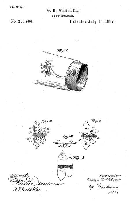
In the accompanying drawings, Figure 1 represents the clasp in position upon the sleeve and its connection with the cuff-button. Figs. 2, 3, and 4 represent detail views of the clasp. Fig. 5 is a modification.
In the drawings I have represented a convenient ornamental form in which the invention may be embodied. In this form there are two wings, a a, which may be struck up or otherwise formed out of precious plated or rolled metal. These wings are provided with hinges, by means of which they are hinged, being cut and turned at right angles to the plane of the wings, as shown at c. There are two hinges upon each wing, and there is a hole made in each hinge, and when the hinges are properly placed together the holes register in the wings, so that a pin, b, may be inserted and complete the hinge. The hinges, instead of being formed out of the metal of the wings, may be soldered thereto. A coiled spring, d, is interposed between the hinges, and the pin when inserted is run through the center of the coil, while the ends of the spring, projecting in opposite directions," bear upon or are fastened to the back of the wings, as shown at e e. Pressure of the spring tends to force the wings downward.
On the under side of the wings, and at their inner edges, are arranged hooks or claws /, preferably two on each wing. The ends of these are turned inward toward each other, and when the wings are drawn backward and pressed together the hooks or claws are opened. The reaction of the spring closes forcibly and drives them into the fabric, where it holds them with a secure grip.
Instead of pivoting the wings upon a pin, I may, as shown in Fig. 4, provide a spring of sufficient length to pass through the hinges of the wings, and secure the spring to the wings, so that it takes the place of the pivot-pin, and at the same time puts the parts under proper tension.
The hooks or claws may be formed out of the metal of the wings, or may be soldered thereto. A fine ornamental chain may be attached to this article by connection with a loop formed on the end of the pin, on which it is hinged, and this chain may be connected at the other end to a cuff or any other ornamental article of personal wear, for securing the same against displacement or loss. The article may be made to imitate a winged insect, or it may have any desired ornamental form.
It will be understood that the ornament may be used as a lace or scarf pin, or in other situations independent of or in connection with any other article of jewelry.
I am aware that prior to my invention a fastening device has been provided consisting of wings having hooks upon their under surface adapted to be opened by pressing the wings together, with a spring between the wings for returning them to their normal position, and I do not broadly claim this as my invention.
I claim as my invention—
1. A clasp consisting of wings having hinges, a central spring passing through hinges on the wings, and hooks or claws on the wings arranged to be closed by the spring, substantially as described.
2. A cuff-holder consisting of a pin having a chain connecting said pin with the cuff or like button, and a fastening device combined with the pin, consisting of wings, a central spring passing through hinges on the wings, and hooks or claws on the wings for connection with the sleeve, substantially as described.
In testimony whereof I have signed my name to this specification in the presence of two subscribing witnesses.
George K. Webster
Witnesses:
Fred. B. Byram
Annie C. Bailey

- He was issued patent number 440,081 on 4 Nov 1890
GEORGE K. WEBSTER, OE NORTH ATTLEBOROUGH, MASSACHUSETTS.
BREASTPIN.
SPECIFICATION forming part of Letters Patent No. 440,081, dated November 4, 1890.
Application filed April 4, 1890, Serial No, 346,530
To all whom it may concern:
Be it known that I, George K. Webster, of North Attleborough, in the county of Bristol and State of Massachusetts, have invented a new and useful Improvement in Breastpins and the Like; and I do hereby declare that the following is a full, clear, and exact description of the same.
The object of my invention is to provide means for securing the catch and pin-joints of breastpins and like articles of jewelry in such a manner as to prevent the turning action of the joints in the material of which the ornament is made. Ordinarily these fastenings are secured to the pearl or other similar material constituting the body of the ornament by simply drilling through from one side to the other, passing the stem of the pin which is connected to the joint or catch through and heading it down upon the front side of the ornament, leaving it thus exposed, or covering it, as may be found desirable; but in this method of securing the catch or pin-joint it has been found that after very little use the stems become loose and are liable to turn, so as to get out of alignment with the opposite part.
To this end my invention consists in providing the stem of the catch or the stem of the pin-joint with a squared shoulder and fitting this shoulder with a corresponding depression or countersink in the under face of the ornament, the stem passing through, as in the ordinary way, this arrangement preventing any lateral displacement or swiveling movement, as referred to, above.
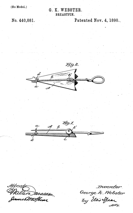
In the accompanying drawings, Figure 1 represents a sectional view of a breastpin provided with my improvement, and Fig. 2 is a plan view.
While I have shown my invention as applied to breastpins, I desire it be understood that I no not limit myself in this respect, but may utilize the idea for use with the stems of ear-rings, studs, and articles of a like nature.
In the drawings, A represents the ornament, which is provided with a catch a and a pin o, which is pivoted between the walls b', secured to or formed with the stem c, constituting the pin-joint. A hole is drilled through the ornament near one end, and through this the round stem of the catch passes. This stem is provided with a shoulder, as shown at d, and this shoulder has flattened sides. A countersink corresponding to the shape of the shoulder is formed in the under face of the ornament at the entrance of the round opening, and thus when the end of the pin is headed down on the face of the ornament the shoulder fits its countersink snugly, and all turning of the catch is prevented.
While I have described the stem of the catch as round and provided with a square shoulder, I do not limit myself to this construction, as it is possible to obtain the same results by providing a square hole adapted to receive a stem square in cross-section. The stem of the pin-joint may be made in precisely the same manner; but instead of forming a squared shoulder on the stem the countersink may be made of sufficient depth to engage the flattened walls of the cap, between the walls of which the pin is pivoted. As these walls are approximately parallel to each other, they serve the same purpose as the squared shoulder of the catch.
Instead of passing the stem entirely through the material of the ornament and heading it down, I may in some cases drill only partly through, fasten the stem by a strong cement, the shoulder or squared stem preventing turning.
I claim as my invention—
1. In combination with the ornamental part of a breastpin, a catch having a stem, and a non-circular shoulder adapted to fit a countersink of corresponding shape, substantially as described.
2. In combination with the ornamental part of a breastpin, a pin-joint having a stem and a cup-shaped part adapted to receive the end of the pin, said cup-shaped part being non-circular in cross-section and adapted to a corresponding recess in the under face of the ornament, substantially as described.
3. In combination, a catch having a stem with a square shoulder fitting a corresponding recess, and a pin-joint having a stem, said pin-joint fitting a recess in the under face of the ornament, substantially as described.
In testimony whereof I have signed my name to this specification in the presence of two subscribing witnesses.
Geo. K. Webster
Witnesses:
W. H. Pond
J. E. Pond
George married Harriet Abigail Richards, daughter of Frederick W. Richards and Abigail Hall, in 1877 in Attleboro MA. (Harriet Abigail Richards was born about 1854 in Attleboro MA.)
|


