Seth William Babbitt
- Born: 13 Sep 1845, Albany NY
- Died: 24 Oct 1913, Meriden CT
General notes:
Pewtersmith
Events in his life were:
- He appeared on the census in 1870 in Meriden CT. Listed as a britannia worker, living in his father's household.
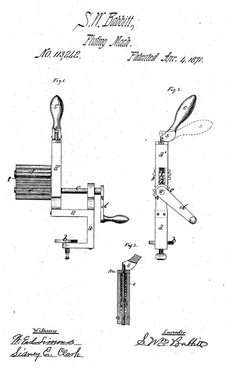
- He was issued patent number 113,242 on 4 Apr 1871
S. WILLIAM BABBITT, OF WEST MERIDEN, CONNECTICUT.
Letters Patent No. 113,242, dated April 4, 1871.
IMPROVEMENT IN FLUTING-MACHINES.
I, S. William Babbitt, of West Meriden, in the county of New Haven and State of Connecticut, have invented certain Improvements in Fluting-Machines, of, which the following is a specification.
Nature amd Objects of the Invention.
My machine is designed for fluting or crimping cloth, and consists of two metal rolls fitting and turning together very much as two gear-wheels turn together. These rolls are removable from their axes and the axes are supported at one end only.
My machine is designed mainly for household use, and is made with a screw-clamp for the purpose of securing it to a table. All fluting-machines use heated rolls, and the heating is usually effected by having one or both the rolls hollow, for the purpose of introducing therein from time to time bars of hot iron.
My improvements consist—
First, in making the rolls detachable from their axes, so that they may themselves be heated.
Second, in having the axes of the rolls supported from one end only, thus leaving the rolls fully open at the other end.
Third, in a novel adjustment for separating the rolls when desired.
Fourth, in attaching a clamp to the machine so that it can be readily fastened to the table.
Description of the Accompanying Drawing.
Figure 1 is a side elevation.
Figure 2 is an end elevation of the end, upon which is the crank.
Figure 3 is a central vertical section of the main upright, showing the construction of my peculiar adjustment for separating the rolls when desired.
General Description.
The letter a indicates the metal frame of the machine, and
b, the screw-clamp for securing it to a table.
The letter e indicates the shaft of the lower roll, bearing the hand-crank d.
The lower roll e is fast to its shaft e.
The upper roll f is loose upon its shaft, and is driven-by the lower roll.
Duplicates of the loose upper roll are necessary, so that while one is in use the other is being heated.
As the roll f is loose upon its axis it is readily slipped off and replaced by its duplicate when desired; or, if preferred, the roll f can be secured upon its shaft by a wire pin, g.
The axis h of the upper roll is square at one end, just sliding in a slot, i, in the upright a', and it is fastened on the rod k which runs through it.
This rod k slides up and down in the bearing m which caps the upright a', and also in the bearing n below the slot i.
A spiral compression-spring, o, bearing against the cap m, on one side and against the square head of the axis or shaft h on the other, forces the upper roll down upon the lower with the necessary force.
The rod k is jointed at the top to the cam s, which has a handle, s', and when this handle is thrown down into the position shown by the dotted lines in fig. 2, the upper roll will be raised to the position shown by the dotted lines in fig. 2, when the cloth can be introduced between them or the rolls changed, a cold one taken off and a hot one put on.
I do not claim, broadly, rolls supported only at one end, nor the adjustment of a movable roll with relation to a fixed one by means of a cam-lever and other devices; but
I claim as my invention—
A fluting-machiue, composed of the hollow removable roll f mounted loosely on shaft h, having a vertical movement in the slot i of the upright a', the rod k, spring o, and cam-lever s s, the roll e, shaft c, and crank d, and the frame a a a' provided with the screw-clamp o, all constructed, arranged, and operating substantially as herein described.
S. Wm. Babbitt
Witnesses:
W. Ed. Simonds
Sidney E, Clark
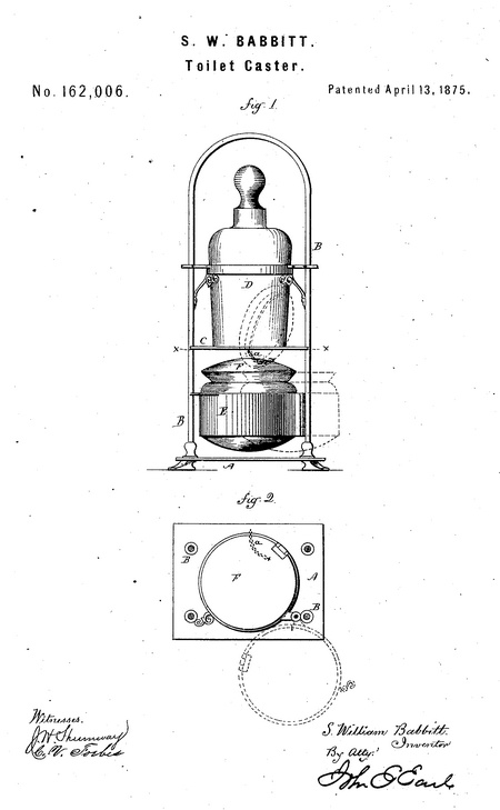
- He was issued patent number 162,006 on 13 Apr 1875
S. WILLIAM BABBITT, OF WEST MERIDEN, CONNECTICUT, ASSIGNOR TO WILCOX SILVER-PLATE COMPANY, OF SAME PLACE.
IMPROVEMENT IN TOILET-CASTERS.
Specification forming part of Letters Patent No. 162,006, dated April 13, 1875; application filed December 16, 1874.
To all whom it may concern:
Be it known that I, S. William Babbitt, of West Meriden, in the county of New Haven and State of Connecticut, have invented a new Toilet-Caster; and I do hereby declare the following, when taken in connection with the accompanying drawings and the letters of reference marked thereon, to be a full, clear, and exact description of the same, and which said drawings constitute part of this specification, and represent, in—
Figure 1, front view; Fig. 2, a sectional plan view, cutting through x x.
This invention relates to an improvement in the manner of combining pots with caster-frames, having special reference to toilet-casters, but applicable to other caster-frames, such as wine-casters, table-casters, &c.; and the invention consists in hinging the pot to the frame upon a vertical pintle, so as to swing from the frame in a horizontal plane when it is desired to reach the contents in the pot, and connecting the cover to the frame so that in swinging out the pot the cover will be automatically opened, and be closed when the pot is returned, as more fully hereinafter described.
A is the base of the caster-frame; B B, the uprights 0, the platform on which the bottles rest, here represented by a single bottle, D. Beneath the platform 0 the pot E is arranged, and is hinged to one of the uprights, or to other convenient part, so as to be swung out from beneath the platform 0, as denoted in broken lines. The pot is provided with a hinged cover, F, the hinge arranged upon or near the rear side, and to the cover a connection, a, is made, by a chain or otherwise, to some part of the frame, so that in swinging-out the pot the connection a will hold upon the cover and cause it to open, as denoted in broken lines ; then, when the pot is returned, the cover will close by its own gravity. Such a construction and arrangement of a pot is applicable to toilet-casters, as a powder-box; to wine-casters, for sugar; to table-casters, for mustard and like condiments; to pitcher-casters, as a slop-receiver.
I therefore do not confine myself to any particular form of caster-frame, it only being essential that the bottle-holder be above the pot. By the term bottle I embrace any article usually supported in a caster-frame, substantially such as before mentioned.
I claim—
The combination, in a caster, of the base which supports the bottle or bottles, the pot E, hinged to the frame below the said base, the cover F, hinged to the pot, and connected to the frame, substantially as described, so that turning the said pot from beneath the base will cause the opening of the cover, and returning the pot will close the cover.
S. Wm. Babbitt
Witnesses:
John H. Bario
Addie C. S. Bario
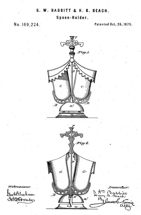
- He was issued patent number 169224 on 26 Oct 1875
S. WILLIAM BABBITT AND HENRY B. BEACH, OF WEST MERIDEN, CONNECTICUT, ASSIGNORS TO THE WILCOX SILVER-PLATE COMPANY, OF SAME PLACE.
IMPROVEMENT IN SPOON-HOLDERS.
Specification forming part of Letters Patent No. 169,224, dated October 26, 1875; application filed August 5, 1875.
To all whom it may concern:
Be it known that we, S. WILLIAM BABBITT and HENRY B. BEACH, of West Meriden, in the county of New Haven and State of Connecticut, have invented certain new and useful Improvements in Spoon-Holder and Call-Bell, of which the following is a specification:
This invention relates to a new and improved ornamental spoon holder or receptacle.
Our invention consists in a circular or other shaped base supporting a bracket, to which are secured two cup-shaped receptacles, united to the handle at the top, substantially as described.
In the drawing, Figure 1 represents an elevation of our improved spoon-holder, and Fig. 2 a sectional view of the same.
The letter A represents the pedestal, which may be of any desired shape or design. In the present instance it consists of an annular base-piece, a, supporting a circular gong or call-bell, a'. To the top of said base, at its center, is secured, in any convenient manner, a branching bracket, B, each branch of which supports a spoon-receptacle, consisting of an ornamental open vase, C. The two vases are united at their adjoining top edges by means of an ornamental standard extending upward, and forming a handle for the article. D represents a rod or wire extending down through the handle, between the vases, and through the center of the bracket, terminating under the bell in position to operate the end of the lever E, which carries the hammer for striking the bell. The upper end of the rod terminates in an ornamental finger-button, F, for the purpose of operating the same.
The holder or receptacle may be constructed of any suitable material, but is intended principally, however, to be made of silver or plated ware, and the vases may be of any approved design.
In the present instance the vases consist of two cup-shaped vessels, the edges of the two being gradually raised toward each other, and their point of attachment to the upright standard, said edges being represented as folded over, forming a suspended border resembling drapery, which may be variously ornamented.
The vases may be arranged in various positions toward each other, but are preferably set obliquely, as shown, which position will be found most convenient for the ready insertion and removal of the spoons. The brackets upon which the vases are supported may be made of various designs, and ornamented to suit the taste, and may be constructed with a continuation or standard extending upward between the two vases, forming a handle for the holder, in place of the standard attached to the tops of the two vases, as above described. The standard thus formed may be made hollow or bored for the introduction of the wire for operating the bell-hammer.
Having thus described our invention, what we claim, and desire to secure by Letters Patent, is—
A spoon-holder consisting of the base A, supporting the bracket B, to which are attached the receptacles or cups C, united at their tops with the handle of the utensil, substantially as described. In testimony that we claim the foregoing we have hereunto set our hands in the presence of the subscribing witnesses.
S. Wm. Babbitt
Henry B. Beach
Witnesses:
A. Chamberlain, Jr.
Henry Berry
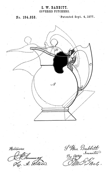
- He was issued patent number 194,858 on 4 Sep 1877
S. WILLIAM BABBITT, OP WEST MERIDEN, CONNECTICUT, ASSIGNOR TO WILCOX SILVER PLATE COMPANY, OF SAME PLACE.
IMPROVEMENT IN COVERED PITCHERS.
Specification forming part of Letters Patent No. 194,858, dated September 4, 1877; application filed June 30, 1877.
To all whom it may concern:
Be it known that I, S. William Babbitt, of West Meriden, in the county of New Haven and State of Connecticut, have invented a new Improvement in Covered Pitchers; and I do hereby declare the following, when taken in connection with the accompanying drawings and the letters of reference marked thereon, to be a full, clear, and exact description of the same, and which said drawings constitute part of this specification, and represent a sectional side view.
This invention relates to an improvement in that class of pitchers and like articles which are provided with covers, which must be opened when tilted for the purpose of pouring out the contents, the object being such a construction as will automatically open the cover when the pitcher is tilted, and insure its automatic closing when set upright.
The invention consists in a cover hinged to the vessel opposite the pouring-spout, combined with a handle jointed to the vessel below the hinge of the cover, and connected to the cover near its hinge, so that, drawing the upper end of the handle backward, as in lifting or tilting the pitcher, the cover will be raised and remain open until the pitcher is set upright and the handle released; then the cover closes by its own weight, returning the handle to its normal condition.
In illustrating the invention it is shown as applied to a pitcher; but it will be understood that the vessel may be other than a pitcher, and of any desirable shape.
A is the body; B, the cover hinged to the body at a in the usual manner; C, the handle, the general form of which is immaterial, hinged to the body, as at d, below the hinge of the cover. Its upper end connection with the cover is here represented by a projection, e, on the cover above the hinge, and a corresponding projection, f, on the handle; hence, if the upper end of the handle be drawn backward, it will correspondingly move the projection e, and with it the cover, which turns up from the front and opens the pitcher. If the handle be taken in hand, as for lifting or tilting the pitcher, as seen in broken lines, the power exerted in lifting, or the weight of the pitcher, causes such a movement of the handle and pitcher from each other that the cover will be raised; then, when the pitcher is again set upright and the handle left free, the cover will close of its own gravity, drawing the handle forward into its normal condition.
A stop, h, is arranged to arrest the opening so soon as the desired extent is attained.
The connection between the cover, made as shown, leaves the cover free to be opened wide without movement of the handle; but the connection may be positive. In such case the extent of movement should be sufficient to open the cover wide.
By the term "pouring-spout" it is not intended to limit this invention to vessels which have a pouring-spout, but the term is used as defining a point in the pitcher opposite the handle, and over which the contents are naturally poured.
I do not broadly claim a pitcher having the cover arranged so that it is automatically opened by means of the handle, as such I am aware is not new.
I claim—
The combination, in a pitcher or similar article, of the hinged cover, the handle hinged at its lower end to the body of the pitcher, and connected at its upper end to the body of the pitcher, so as to allow it to swing toward and from the hinge of the cover, and a connection between the handle and cover, substantially as described, so that the movement from the pitcher opens the cover, substantially as specified.
S. Wm. Babbitt
Witnesses:
A. L. Otis
W. H. H. Santy
- He was issued patent number 196,180 on 16 Oct 1877
S. WILLIAM BABBITT, OF WEST MERIDEN, CONNECTICUT, ASSIGNOR TO WILCOX SILVER PLATE COMPANY, OF SAME PLACE.
IMPROVEMENT IN COVERED ARTICLES OF PLATED WARE.
Specification forming part of Letters Patent No. 196,180, dated October 16, 1877; application filed October 2, 1877.
To all whom it may concern:
Be it known that I, S. Wm. Babbitt, of West Meriden, in the county of New Haven and State of Connecticut, have invented a new Improvement in Covered Articles of Plated Ware; and I do hereby declare the following, when taken in connection with the accompanying drawings, and the letters of reference marked thereon, to be a full, clear, and exact description of the same, and which said drawings constitute part of this specification, and represent, in—
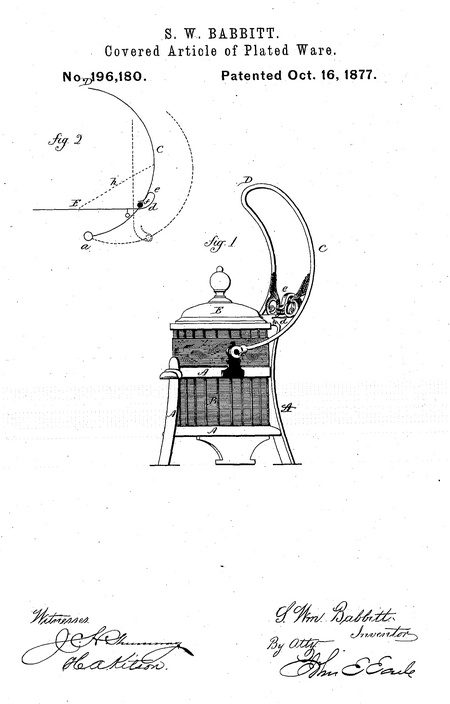
Figure 1, perspective view; Fig. 2, diagram illustrating the operation.
This invention relates to an improvement in covered articles for table - service, such as pickle-jars, &c, in which the handle is of bail-shape, hinged to the supporting-frame, and extending above the cover, the object being to connect the bail with the cover, so as to automatically open or close the cover; and the invention consists in a bail hinged to the article below the cover, and extending up above, so as to form a bail-shaped handle, and connected with the cover between the handle proper and the hinge of the bail, so that, by turning the bail backward, the cover will be raised, as more fully hereinafter described.
The article of table-service here represented is a pickle-jar, which consists of a frame, A, of any desirable pattern, constructed to receive and hold the jar B. At opposite points on the frame, as at a, the bail C is hinged, and. extends upward and over the cover, so that, taking hold at the top of the bail, the article may be raised, and carried in the usual manner for such articles. Preferably the bail is curved backward between the handle D and the hinge a. The cover E is hinged in the usual manner, and connected with the. bail, as here represented, by an extension, d, rearward, the extension turning upward and forward, forming a hook shape, e, through which a bar, f, on the handle passes.
The operation of this construction is illustrated in Fig. 2. Raising the article by taking hold at D has no effect upon the cover, it being substantially the center of gravity of the article, and the article is raised and carried about in the usual manner for such articles. When desired to open the cover, the hand, still holding at D, presses backward, and the bar/ depresses the extension d of the cover until the cover is opened, as indicated in broken lines, and when the handle is returned the cover will close, thus making the opening and closing of the cover automatic.
Instead of the projection d and the barf a rod or flexible connection may be made between the cover and the handle, as indicated by the line h, Fig. 1, and the same result accomplished. The particular connection, therefore, between the cover and the bail is not essential.
It will be understood from the foregoing that this construction is applicable to other articles of table, toilet, or other service.
I claim—
In combination with the hinged cover, the bail-shaped handle, hinged below and extending above the cover, and the connection between the cover and the said handle, whereby the said handle may be used as a bail in carrying the article, and also as a means for opening the cover, substantially as specified.
S. WM. BABBITT
Witnesses:
George A. Fay
H. N. Waters
- He was issued patent number 199,010 on 8 Jan 1878
S. WILLIAM BABBITT, OF WEST MERIDEN, CONNECTICUT, ASSIGNOR TO WILCOX SILVER PLATE COMPANY, OF SAME PLACE.
IMPROVEMENT IN COVERED BUTTER-DISHES.
Specification forming part of Letters Patent No. 199,010, dated January 8, 1878; application filed December 19, 1877.
To all whom it may concern:
Be it known that I, S. Wm. Babbitt, of West Meriden, in the county of New Haven and State of Connecticut, have invented a new Improvement in Covered Butter-Dishes; and I do hereby declare the following, when taken in connection with the accompanying drawings and the letters of reference marked, thereon, to be a full, clear, and exact description of the same, and which said drawings constitute part of this specification, and represent, in—
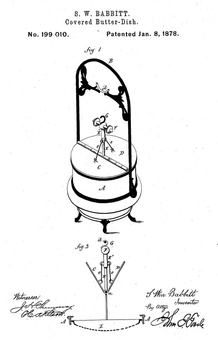
Figure 1, a perspective view; Fig. 2, a sectional view.
This invention relates to an improvement in articles of table-service which are provided with covers, such as a butter-dish, pickle-jar, &c. Therefore, while styling this as "butterdish," it is intended to be understood as applying to articles similarly provided with a cover ; and it consists in a divided cover hinged at the center, combined with a lifting device, whereby, when the two covers are raised bodily, they will at the same time be turned upward upon their hinges, and as more fully hereinafter described.
A represents the dish, which may be of any desirable form or style, from which a bail, B, extends upward, as a convenient means for carrying or moving the dish; C, one part, and D the other part, of the cover, hinged together at the center a—that is to say, both hinged at substantially one point. From the pintle, or part to which the two covers are hinged, an upright, E, rises, and on this is a vertical sleeve, E', terminating in a handle, F, and so as to slide freely up and down on the upright E. The handle F is provided with a hook or other device, G, by which, when raised, it may be attached to a suspending-point. d. From the sleeve E' a link, e, extends to each cover. The point at which the links are attached to the cover must be distant from the center so far that the weight of the cover between the links will overbalance the portion of the cover outside. The cover may be weighted at the center, and thereby allow the links to be attached to the cover proportionately nearer the center.
In the representation a plate, L, for the butter-dish is suspended to the cover at each side; hence that constitutes a weight, and is
arranged so as to move freely up and down within the dish.
To open the dish, take hold of the handle F, raise it, and suspend it at the point d, as seen in Fig. 2, which not only raises the covers from the dish, but turns them up on their hinges, as seen in Fig. 2, and also raises the plate L up to near the edge of the dish. This takes the cover entirely out of the way, and avoids the necessity of raising the cover so high as is necessary in that class of dishes in which a solid cover is raised vertically to expose the butter.
The plate may be guided within the dish by means of vertical ribs upon the sides and corresponding notches in the edge of the plate; but this is not essential to the invention.
It is not essential that the upright E should be rigidly connected to the hinging-point of the covers, or that there should be any connection, as the links may be attached directly to the hook; but the handle and sleeve are preferable as being more convenient.
I claim—
1. In a covered dish provided with a bail or suspending-point over the cover, the cover divided into two parts, hinged together, and combined with a connection from each of the said two parts to a common device, by which the covers may be suspended at the said suspending-point, and thereby not only open the dish, but turn the parts of the cover upward on their hinges, substantially as described.
2. In a covered dish in which the dish is opened by raising the cover from the dish, a plate suspended to said cover, and so that raising the cover raises the said plate, and vice versa, substantially as described. .
3. In a covered dish in which the cover is divided into two parts, hinged together, and combined with a connection from each of said parts to a device common to both, so that raising said device both lifts the covers from the dish, and at the same time turns the two parts upward on their hinges, substantially as described.
S. Wm. Babbitt
Witnesses:
John E. Earle
H. A. Kilson
- He was issued patent number 199,772 on 29 Jan 1878
S. WILLIAM BABBITT, OF WEST MERIDEN, CONNECTICUT, ASSIGNOR TO WILCOX SILVER PLATE COMPANY, OF SAME PLACE.
IMPROVEMENT IN COVERED DISHES.
Specification forming part of Letters Patent No. 199,772, dated January 29, 1878; application filed January 14, 1878.
To all whom it may concern:
Be it known that I, S. Wm. Babbitt, of West Meriden, in the county of New Haven and State of Connecticut, have invented a new Improvement in Covered Dish; and I do hereby declare the following, when taken in connection with the accompanying drawings and the letters of reference marked thereon, to be a full, clear and exact description of the same, and which said drawings constitute part of, this specification, and represent, in—
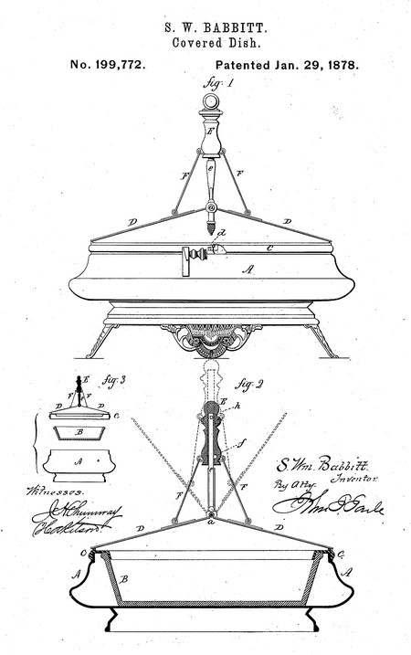
Figure 1, a side view; Fig. 2, a vertical central section; and Fig. 3, the three parts detached.
This invention relates to an improvement in articles or dishes for table service and other purposes, and particularly to that class of plated ware in which a porcelain pan is introduced into the body of the plated portion, and its edge covered by a band extending over the edge both of the body and the said pan, and commonly called "pudding-dishes," but parts of the invention are applicable to other dishes and uses; and the invention consists in the construction and combination of parts, as hereinafter described, and more particularly recited in the claims.
For convenience of illustration, the invention is shown as applied to a pudding-dish, and in which A represents the base or body, constructed to receive within it a porcelain-lined pan, B. C the hoop or band, which overlaps both the body and the pan, so that the edge of both are concealed, and the separation of the parts is not apparent.
In this class of dishes a cover is generally used in a single piece, and to simply sit on over the band C; and to remove it, it must be entirely detached from the band, thus making the dish in four parts.
In order to combine the cover with the band, and thereby practically lessen the number of parts, there is a cover in two parts, D D, hinged at the center to a pintle or bar running across from one point of the band C to the opposite, and preferably this hinged point a is raised on the said central or hinged line, causing the covers, when closed, to lie in an inclined position, as seen in Figs. 1 and 2. Thus the band and cover are made substantially one and the same, and so that the dish may be opened by raising either one or both covers; and a handle applied to the said central bar serves as a convenient means for carrying the dish. In order that the dish may be lifted by such handle, the band C is locked to the body A by a bayonet or other suitable joint, as at d, Fig. 1, where a portion of the band is broken away to show the locking device. By unlocking these parts they may be separated, as seen in Fig. 3; or when locked together the whole may be lifted as one article by taking hold of the handle.
In order to automatically open the covers, a post or guide, e, is centrally attached to the cross-bar, and onto this a vertically-sliding handle, E, is placed, and so as to move freely up and down thereon within certain limits. From this handle E a connection, F, is made from each side to the cover, and so that when the handle is raised the covers will, by Such connection, be drawn up, as seen in Fig. 2, to open the cover. This will occur in lifting the dish by the handle, so that the servant in passing it will present it in an open condition.
When standing on the table it is desirable at times to sustain the covers in their open condition. To do this a notch, f, is made in the sleeve, and a correspondingprojectiiigstud, h, on the post e, and so that when the handle and covers are raised, as seen in broken lines, Fig. 2, the handle may be partially turned to bring the stud into the notch f, and, there resting, support the handle and covers in that condition; or, instead of the notch f, the handle may be raised entirely above the stud, and accomplish the same result.
The connection between the handle and the covers may be made in various ways, as, for instance, it may be chains or rods; or the handle may be extended down to the covers, and make a simple hook engagement; or, instead of lifting the handle to open the covers it may be simply rotated, the connection of the covers being so that such rotation will act to raise the covers, as by worm and segment.
It is therefore to be understood that this invention is not limited to the particular arrangement for lifting the covers shown in illustration.
As before stated, and by the foregoing description, it will be evident that this invention and parts of it are applicable to other dishes or articles, and the invention is therefore not limited to any particular class of dishes.
I claim—
1. The combination of the body A, the inner pan B, band C, and a cover hinged to the said band, substantially as described.
2. The combination of the body A, the inner pan B, the band 0, and a cover hinged thereto, with a locking device between the
said band and the body, substantially as described, and for the purpose of "securing the parts together.
3. In a covered dish, a divided cover, the two parts hinged permanently to the band, combined with a lifting-handle in connection with said covers, and so that by said handle the covers may be lifted, substantially as described.
S. Wm. Babbitt
Witnesses:
Chas. H. Shaw
Charles B. Goodrich
- He was issued patent number 204,784 on 11 Jun 1878
S. WILLIAM BABBITT, OF WEST MERIDEN, CONNECTICUT, ASSIGNOR TO WILCOX SILVER PLATE COMPANY, OF SAME PLACE.
IMPROVEMENT IN COVERED DISHES.
Specification forming part of Letters Patent No. 204,784, dated June 11, 1878; application filed May 25, 1878.
To all whom it may concern:
Be it Known that I, S. Wm. Babbitt, of West Meriden, in the county of New Haven and State of Connecticut, have invented a new Improvement in Covered Dishes; and I do hereby declare the following, when taken in connection with' the accompanying drawings and the letters of reference marked thereon, to be a full, clear, and exact description of the same, and which said drawings constitute part of this specification, and represent, in—
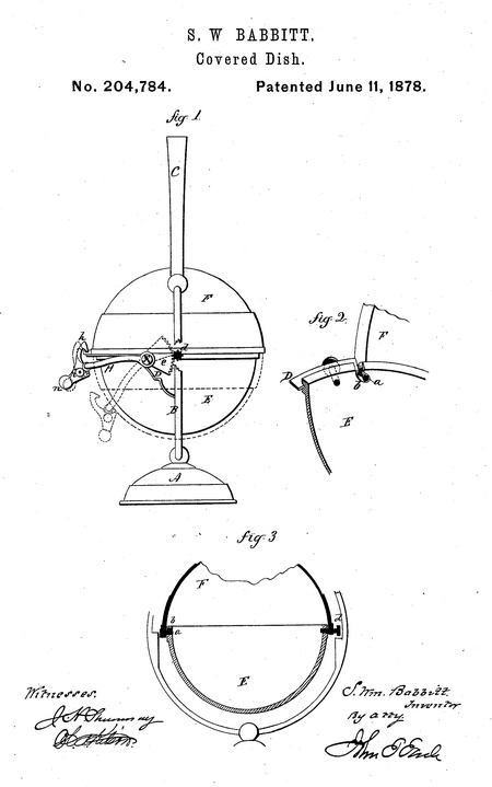
Figure 1, side view, a portion of the frame broken away for full illustration. Fig. 2, detached view; Fig. 3, vertical section.
This invention relates to an improvement in that class of covered dishes such as used in table service for butter, but applicable to other uses, and in which the cover is hung upon trunnions diametrically opposite each other, so as to be turned over from and down beneath the body of the dish to open it; and the invention consists in the construction, as hereinafter described, and more particularly recited in the claims.
A is the base, from which an upright, B, rises each side the dish, extends up above, and terminates in a bail or handle, C. On one side of the upright B there is a semicircular frame, D, which extends from the upright on one side to the upright oa the other. E, the bowl or body of the dish, which is usually of hemispherical form, is attached to the frame D, and so as to be supported by it. Its connection may be by screws through the frame or equivalent fastening. F is the cover, corresponding in shape to the body, but so much larger that it may turn beneath the body, as indicated in broken lines. On one side of the cover there is a trunnion, a, as seen in Fig. 2, where the cover is shown as partially turned away from the dish. This trunnion projects inward and sits in an L-shaped recess, b, in the side of the bowl. On the opposite side there is a similar trunnion extending into the body of the dish, and these trunnions form the pivots on which the cover revolves and may be turned upward over the dish to close it, resting at one side on the frame D, as shown in Fig. 1, or turned beneath the dish, as indicated in broken lines.
To afford a convenient means for thus opening and closing the cover, apinion, d, is attached to the cover in the axial line of one of the trunnions, and working in this pinion is a segment, e, hung upon a pivot, f, and from the segment at the pivot a rod, H, extends around the dish, and so that the said rod H forms a lever by which to operate the segment e. Hinged to this lever is a latch, h, which, when the cover is closed, hooks over the frame D, or a projection thereon, as shown in Fig. 1. This latch is hinged to the lever H at i, and with a handle, n, projecting outward from the pivot.
To open the cover, depress the handle n, as indicated in broken lines, which turns the latch from its connection with the frame, as seen in Fig. 1, and a continued depression turns the segment, which, working in the pinion, correspondingly turns the cover. To close the cover, take hold, of the handle n and raise it. A reverse operation through the pinion closes the cover, and at the same time brings the latch into engagement with the frame.
This arrangement is applicable to covers that are hung upon trunnions differently arranged from that hereinbefore described; but by this arrangement the trunnions can be made solidly upon the cover, and not required to be removed to detach the cover. The trunnion on one side, as seen at the right hand in Fig. 3, may be first introduced from the outside of the dish, through a corresponding perforation in the side of the dish. Then the other, a, may be passed into the notch b before the dish is secured to the frame, and as that notch turns at right angles, as shown, a portion of the dish overhangs the trunnion a; and when the dish or body E is pressed up to place and secured the end .of the frame D prevents the trunnion a from passing forward, so as to escape from the notch, and as seen in Fig. 2.
The screws which secure the dish to the frame may be, and preferably are, the pivots on which the segment turns, the lever extending from one side to the other of the dish.
While specially designed for butter-dishes, this construction is applicable to other articles of table service, and to other purposes, as jewel-cases, work-cases, &c.
I claim—
1. The combination of the body E of the dish, the frame D for supporting the body, and
to which it is attached, the revolving cover F, with trunnions connecting it with the body, and so that securing the body to the frame secures the cover in place, substantially as described.
2. The combination of the body E, revolving cover F, a pinion on the axis of the said cover, a segment working in said pinion, with handle and latch for operating and securing said segment, substantially as described.
S. Wm. Babbitt
Witnesses:
James P. Platt
Henry Drylesworth
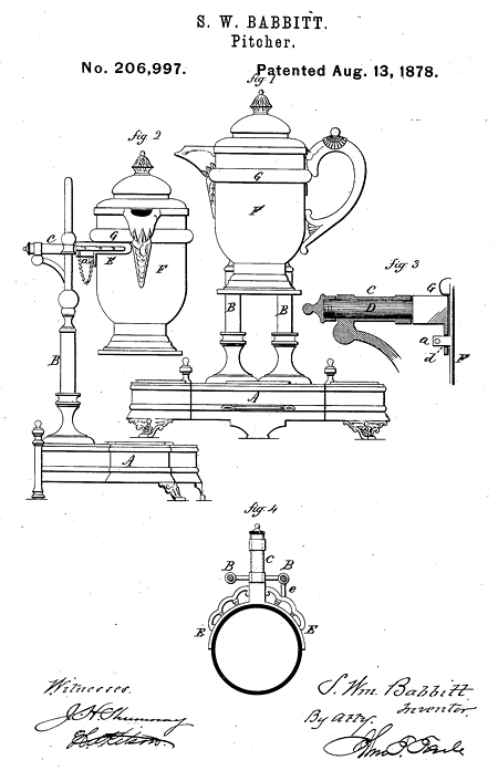
- Patent: 206,997, on 13 Aug 1878. S. WILLIAM BABBITT, OF WEST MERIDEN, CONNECTICUT, ASSIGNOR TO WILCOX SILVER PLATE COMPANY, OF SAME PLACE.
IMPROVEMENT IN PITCHERS.
Specification forming part of Letters Patent No. 206,997, dated August 13, 1878; application filed July 20, 1878.
To all whom it may concern:
Be it known that I, S. William Babbitt, of West Meriden, in the county of New Haven and State of Connecticut, have invented a new Improvement in Water-Pitchers; and I do hereby declare the following, when taken in connection with the accompanying drawings and the letters of reference marked thereon, to be a full, clear, and exact description of the same, and which said drawings constitute part of this specification, and represent, in—
Figure 1, a front view; Fig. 2, a side view; Figs. 3 and 4, detached views.
This invention relates to an improvement in that class of pitchers which are hung upon a pivot, and so as to be tilted without lifting the pitcher, automatically resuming its vertical position when left free from the force which tilted it.
In the usual construction of this class of pitchers they have been hung upon a pivot upon each side, leaving the spout at the front.
In this construction the pitcher is almost entirely hidden by the frame-work which supports it, and the frame-work itself generally interferes with the convenient tilting of the pitcher.
The object of this invention is to suspend the pitcher at a single point, thereby leaving the handle, spout, and front side of the pitcher as free of access as if it were not suspended, and in such construction the invention consists.
A represents the base, which may be of any desirable form, at one side of which a support,
B, rises, here composed of two posts. In this support, above the base, a horizontal socket,
C, is formed, and in this a spindle, D, rests, carrying a yoke, E. This yoke lies in a horizontal plane, and corresponds to the shape of the pitcher P.
The pitcher is constructed with a rib or projection, G-, which will rest upon the upper surface of the yoke, and so that the pitcher will be supported thereby; and in order to secure the pitcher to the yoke a stud, a, is formed on the side of the pitcher, and so as to pass through a perforation, d, in the yoke, and be there secured by passing a pin through the stud or otherwise; or other attachment may be made to secure the pitcher on the yoke, it being understood that the attachment is made so that the spindle D is at right angles to the vertical plane through the spout and handle, as shown. This construction leaves the opposite side, or practically the front of the pitcher, free as if the pitcher stood upon a waiter, and it may be tilted without any inconvenience from the supporting device, and when occasion requires the removal of. the pitcher it is only necessary to disconnect it from the yoke.
To insure the pitcher resting in its vertical position, a stop, c, extends outward from the support on the side of the socket next the handle to beneath the yoke, and so that the yoke will rest thereon when the pitcher is in its vertical position. The handle being heavier than the spout overbalances that, and tends to bring the pitcher back to the position of rest after it has once been tilted.
From the foregoing it will be understood that no broad claim is made to suspending the pitcher so that it may be tilted; but
What is claimed as new, and desired to be secured by Letters Patent, is—
1. A support for tilting pitcher, consisting of a single socket or pivot, and a yoke or rest arranged to turn in the said socket, combined with a pitcher supported in said yoke or rest, substantially as described.
2. A support for tilting pitcher, consisting of a single socket or pivot, and a yoke or rest arranged to turn in the said socket, combined with a pitcher supported in said yoke or rest, and a device, substantially such as described, to secure the pitcher in the said rest, substantially as specified.
S. Wm. Babbitt
Witnesses:
A. L. Stevens
W. H. H. Santy
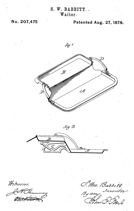
- He was issued patent number 207,475 on 27 Aug 1878
S. WILLIAM BABBITT, OF WEST MERIDEN, CONNECTICUT, ASSIGNOR TO WILCOX SILVER PLATE COMPANY, OF SAME PLACE.
IMPROVEMENT IN WAITERS.
Specification forming part of Letters Patent No. 207,475, dated August 27, 1878; application filed July 26, 1878.
To all whom it may concern:
Be it known that I, S. William Babbitt, of West Meriden, in the county of New Haven and State of Connecticut, have invented a new Improvement in Waiters; and I do hereby declare the following, when taken in connection with the accompanying drawings and the letters of reference marked thereon, to be a full, clear, and exact description of the same, and which said drawings constitute part of this specification, and represent, in—
Figure 1, perspective view; Fig. 2, transverse central section.
This invention relates to an improvement in that class of waiters designed to be carried in the hands of the servant, but is applicable to other uses; and it consists in a principal tray, combined with a second tray- elevated above the principal tray, as more fully hereinafter described.
A represents the principal tray, which may be of any of the usual forms, and having the usual edge upon the front and two ends. At the rear a second or auxiliary tray, B, is arranged, elevated above the first or principal, tray, A, and with an edge around it as a protection to the articles thereon; and, for the purpose of supporting the tray when, set upon the table, one or more brackets, C, is arranged beneath the elevated or auxiliary tray, as seen in Fig. 2. For convenience of carrying the tray, a handle, D, is provided at each end.
This construction adds to the convenience of this waiter, in that articles placed at the rear are elevated above those in the front, so that in reaching over from the front to the articles in the rear the danger of interference with the articles at the front is avoided.
The particular form of the waiter is immaterial to this invention, as that will be changed as the use for the waiter or the demands for the trade may require. The handles are not essential, as the waiter could be held without the handles equally as well as ordinary waiters of like capacity.
The auxiliary or raised tray is represented as offset or set back from the principal tray; but, if desired, the principal tray may extend beneath the auxiliary tray, it only being essential to the invention that the auxiliary elevated tray be made as a part of the principal tray and set back from one edge of the principal tray.
I claim—
The herein-described waiter, consisting of a principal tray and an auxiliary tray, elevated above the principal tray and set back from one edge of the principal tray, substantially as described.
S. Wm. Babbitt
Witnesses:
A. L. Stevens
W. H. H. Santy
- He appeared on the census in 1880 in Meriden CT. Listed as a designer.
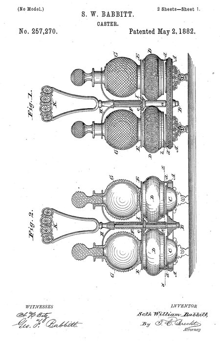
- He was issued patent number 257,270 on 2 May 1883
SETH W. BABBITT, OF MERIDEN, CONNECTICUT.
CASTER.
Specification forming part of Letters Patent No. 257,270, dated May 2, 1883. Application filed February 10, 1882.
To all whom it may concern:
Be it known that I, Seth William Babbitt, a citizen of the United States, residing at Meriden, in the county of New Haven and State of Connecticut, have invented certain new and useful Improvements in Casters; and I do hereby declare the following to be a full, clear, and exact description of the invention, such as will enable others skilled in the art to which it appertains to make and use the same.
My invention relates to improvements in casters, and is applicable to wine-casters, table-casters, &c.; and the object is to produce a caster that is simple in construction, and in which the various articles usually employed for toilet purposes are arranged in an easily-accessible, neat, and compact manner, and that can be conveniently and readily manipulated.
The invention consists in the manner of combining revolving boxes, cups, and bottle-holders with a caster-frame in such manner that any article contained in any of the receptacles is readily and conveniently accessible for use, and said receptacles are arranged in a very compact space.
It also consists in the construction of spring-wire holders open at one side, and by which the bottles are securely held by clamping around the necks of the bottles.
It further consists in certain details of construction, as will be more fully described hereinafter, reference being had to the accompanying drawings and the letters of reference marked thereon.
In the accompanying drawings, Figure 1 represents a side view of my improved caster. Fig. 2 is a vertical cross-section of the same. Fig. 3 is a plan view of the caster with the handle and the bottles removed. Fig. 4 is a horizontal section on line x x of Fig. 2. Fig; 5 is a vertical cross-section on line y y of Fig. 4.
In the drawings, A is the base of the caster-frame, having suitable feet, and to it the upright or standard B is firmly secured. The base is provided at each side of the standard with a hole, A', for the reception of the flanged cups C, which are suspended therein, and are to be used for pomatum, cosmetics, or similar articles.
Immediately above the base A are arranged two boxes or receptacles, D for powder, paint, or similar articles, and these boxes are attached to a sleeve, a, so that they can be easily revolved around the upright B. The boxes (either one or both) are provided with a lug, b, that engages with a notch, c, in the projections d, having inclined faces and secured to the base A, and they serve to hold the boxes in their normal position. When it is desired to revolve the boxes D it is only necessary to slightly raise them, and thus the lug b is disengaged from the notch c. The bottoms of the boxes D serve as covers for the cups C when brought in line with them.
As close as allowable to the month of the boxes D is arranged, a revolving table or platform, E, which is secured to a sleeve, F, so as to be easily revoluble on the standards. Upon, this table the bottle G, for perfumery, oils, or similar articles, are supported and held in place by a spring bottle-holder, H. This holder consists of a double wire of springy metal, and is curved upward and outward, and bent at its outer ends, f, (as best seen in Fig. 8,) so as to embrace and firmly clamp the necks of the bottles when they are placed in position on the table E. The necks of the bot-tles can be easily removed or replaced between the ends f of the holder H. The lower side of the table is provided with a lug, e, which en-gages, when brought in line, with a notch in the collar I, that is secured to the standard B, and serves to hold the table in position. By slightly raising the table the lug e, is disengaged from the notch in the collar I, and can then be readily revolved.
The handle K is secured to the upper end of the standard B and serves to transport the caster from place to place, as desired.
When the caster is to be used as a table-caster the bottles may be filled with vinegar or oil, the boxes with sugar, &c, and the cups with pepper and salt.
It will be readily understood that I do not confine myself to casters, as described, as it can be used as a table-caster, wine-caster, or for any other purpose to which it is applicable; neither do I limit myself to the number of cups, boxes, or bottles, as more than two of each may be employed, If desired.
The various parts constituting the caster can be highly ornamented, and are not liable to get out of order, as they are very simple in construction. It can be easily manipulated,
and the various parts or, articles contained in the cups, boxes, or bottles are readily accessible, and the ordinary covers for the boxes or cups are dispensed with, as the bottoms of the revolving boxes serve as the covers for the cups in the base and the revolving table serves as the cover for the boxes when in their normal position, or when they are brought in line with each other.
Having thus described my invention, what I claim, and desire to secure by Letters Patent, is—
1. In a caster, the cups C, suspended in the base A of the caster-frame, substantially as shown, and for the purpose specified.
2. In a caster, the boxes D, secured to a sleeve and revolable on the standard B, and serving as a cover for the cups C, arranged sub--stantially as and for the purpose described.
3. In a caster, the boxes D, secured to a sleeve revolving on the standard B, and provided with a lug, b, for engaging with a notched projection; d, on the base A, substantially as set forth.
4. In a caster, the boxes D, secured to a sleeve, F, revolving on the standard B, in combination with the suspended cups C in the base A, all arranged substantially as shown, and for the purpose set forth.
5. In a caster, the revolving platform E, for supporting the bottles, and provided with a lug, e, for engaging with a notch in the collar I on the standard B; substantially as specified.
6. In a caster, a spring-holder, H, open at its outer ends, and curved to securely hold the bottles by clamping around their necks, substantially as shown, and for the purpose described.
7. In a caster, the combination of the revolving boxes with the revolving platform for supporting the bottles, and serving as a cover for the boxes, substantially as specified,
8. In a caster, the combination of the suspended cups in the base A with the revolving boxes D and the revolving platform E, arranged substantially as shown, and for the purposes herein set forth.
9. In a caster, the revolving platform secured to a sleeve, F, in combination with the spring bottle-holder, arranged substantially as shown, and for the purpose specified.
10. In a caster, the revolving platform secured to a sleeve, F, and provided with means for holding it in position, in combination with the spring bottle-holder H, open at its outer ends, and serving to hold bottles by clamping around their necks, substantially as herein set forth.
11. In a caster, a revolving platform supporting the bottles, held and clamped by spring bottle-holders, in combination with the revolving boxes and the cups suspended in the base, substantially as shown, and for the pu rpose described.
12. A caster consisting of a base, A, standard B, cups C, revolving boxes D, and revolving table E, for supporting bottles G, held and clamped by spring bottle-holders H, and a handle, K, all arranged substantially as specified.
In testimony whereof I hereby affix my signature in presence of two witnesses.
Seth William Babbitt
Witnesses:
Carl F. Sorg
Geo. F. Babbitt
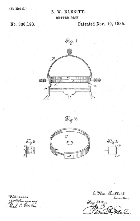
- He was issued patent number 330,193 on 10 Nov 1885
S. WILLIAM BABBITT, OF MERIDEN, CONNECTICUT.
BUTTER-DISH.
Specification forming part of Letters Patent No. 330,193, dated November 10, 1885. Application filed August 12, 1885. Serial No. 174,188.
To all whom it may concern:
Be it known that I, S. Wm. Babbitt, of Meriden, in the county of New Haven and State of Connecticut, have invented a new Improvement in Butter-Dishes; and I do hereby declare the following, when taken in connection with accompanying drawings and the letters of reference marked thereon, to be a full, clear, and exact description of the same, and which said drawings constitute part of this specification, and represent, in—
Figure 1, a vertical central section; Pig. 2, a perspective view of the reversible plate, a portion of the cylindrical rim broken away to show the flange upon both sides, the plate; Figs. 3 and 4, modifications.
This invention relates to an improvement in that class of butter-dishes which are usually made from metal, and in which a disk or plate is arranged within the dish, on which the butter may rest, so that drippings from the ice placed thereon may fall into the dish below the plate, this plate being commonly called a "drainer."
If the plate be made of metal, the cutting of butter on the plate defaces the surface of the plate to a very considerable extent. To avoid the effect of such defacing, the plate has been made from glass or similar vitreous material surrounded by a metal band adapted to set into the body of the dish, the surrounding ring being the same as that of the metal plate, and constructed with an annular shoulder upon its outside to rest upon a corresponding shoulder in the dish. The glass or vitreous plate is expensive, and is not altogether ornamental, and does not have that neat appearance which a metal plate presents if undefaced.
In the use of such dishes for common ordinary family use the defacing of the metal plate does not create a serious objection; but for special occasions the defaced appearance of the plate would be objectionable.
The object of my invention is to construct a metal plate which may be adapted to use for general purposes or upon special occasions, and upon such special occasion present a fresh surface, in contradistinction to the surface defaced by general use; and it consists in a metal disk having an annular rim around its edge, projecting alike upon both surfaces, and so that the plate may be reversed in the dish to present either side of the plate upward, as more fully hereinafter described.
A represents the body of the dish, and B the cover, adapted to set thereon in substantially the usual manner. The body of the dish is constructed with a shoulder, a, upon its inside below the upper edge, upon which the plate may rest. C is the plate, which consists of a disk of metal constructed with an annular cylindrical rim, D, and so as to form a flange, a, upon one side, and b upon the opposite side, of the plate, thetwoflangesbeingof substantially the same extent. The diameter of the rim is such that it may enter the body of the dish and rest upon the shoulder a, as seen in Fig. 1, and there support the butter which maybe placed thereon. Both sides of the plate may be finished alike, or one may be more highly finished than the other. Generally one side is gold-plated and the other silver-plated, to make a strong distinction between the two.
The plate is introduced one side up, and so used. In such use the surface will naturally become defaced, and if upon special occasions a fresh surface be desirable the plate is reversed, to bring the other and undefaced side to the top, and thus the defacing from general use will be hidden and a fresh undefaced surface presented. This construction of plate adds substantially nothing to the cost of the dish, yet the reversibility of the plate gives to it the capacity to be used substantially as two independent dishes.
Instead of making the shoulder upon the inside of the dish for the drainer to rest upon, the drainer may be constructed, as seen in Fig. 3, with an annular rib, d, around its edge, to rest upon the upper edge of the dish, the rib also serving as a seat for the cover, and when set together the rib will form an ornamental bead between the cover and the dish; or the plate may set over the outside of the dish, as indicated in Fig. 4, and the cover within it, as also shown in that figure, the rim of the plate forming an ornamental band around the dish. I therefore do not wish to be understood as limiting the invention to any particular support or arrangement of the plate, further than that it be made with the rim around its edge, and extended so as to form a flange upon both sides of the plate, whereby the plate is made reversible.
I claim—
A butter-dish consisting of a body and a cover, combined with a removable reversible metal plate, the said plate constructed with an annular cylindrical rim around its edge, projecting alike on both sides, the plate adapted to to be supported in the dish, substantially as described.
S. William Babbitt
Witnesses:
Henry B. Beach
Chas. T. Dodd
|


