Gurdon W. Hull
- Born: 17 May 1834
- Marriage (1): Elizabeth Melinda Simpson on 6 Jun 1864 in Wallingford CT
- Died: 10 May 1894, Wallingford CT
General notes:
Silver and pewtersmith
Events in his life were:
- He worked as a silver and pewtersmith circa 1850-1865
- He appeared on the census in 1850 in Wallingford CT. Listed as a spoon maker, living in the home of William Mix.
- He appeared on the census in 1860 in Meriden CT. Listed as a burnisher.
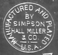
- He appeared on the census in 1870 in Wallingford CT. Listed without occupation, living in the home of his partner and father-in-law, Samuel Simpson.
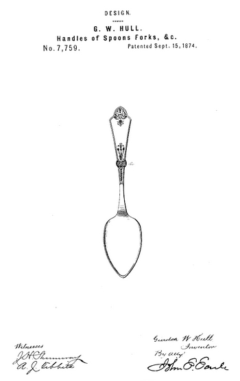
- Patent: 7,759, on 15 Sep 1874. GURDON W. HULL, OF WALLINGFORD, CONNECTICUT, ASSIGNOR TO SIMPSON NICKEL SILVER COMPANY, OF SAME PLACE.
DESIGN FOR HANDLES OF SPOONS, FORKS, &c.
Specification forming part of Design No. 7,759, dated September 15, 1874; application filed September 4, 1874.
[Term of Patent 7 years]
To all whom it may concern: Be it known that I, GURDON W. HULL, of Wallingford, in the county of New Haven and State of Connecticut, have invented a new Design for Spoon and Fork Handle; and I do hereby declare the following, when taken in connection with the accompanying drawings and the letters of reference marked thereon, to be a full, clear, and exact description of the same, and which said drawings constitute part of this specification, and represent a front view.
This invention relates to a design for handle for spoons, forks, and like articles of table service; and consists in the configuration and ornamentation of the handle, as shown in the accompanying illustration.
From the bowl or body the handle gradually contracts for about one-third its length, and then expands to the tip, the line of the edges being slightly curved. About midway of its length is a boss, a, projecting from each side. The tip of the handle is semi-quarterfoil in shape. Below this boss a a simple branch runs down on the surface of the handle, and above the boss a "honeysuckle" branch extends up the surface of the handle to about the same distance as the branch below. A plain bead runs around the edge of the handle from the narrowest point upward, and at the tip runs into a central honeysuckle branch, all as shown in the accompanying illustration.
I claim—
The design for spoon and fork handle, consisting of the curved edges, termainating in the semi-quarterfoil at the tip, the central boss a, the surface, ornamented by a branch above and below the boss, and a bead around the edge, running into the honeysuckle branch at the tip, all as shown in the accompanying illustration.
G. W. Hull
Witnesses:
O. J. Martin
Dwight Hull
- He appeared on the census in 1880 in Wallingford CT. Listed as a britannia manufacturer, living in the home of his father-in-law.
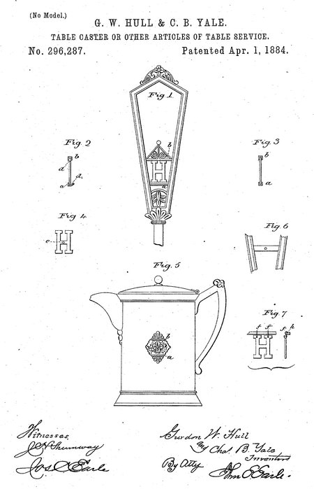
- He was issued patent number 296,287 on 1 Apr 1884
GURDON W. HULL AND CHARLES B. YALE, OF WALLINGFORD, CONNECTICUT, ASSIGNORS TO SIMPSON, HALL, MILLER & CO., OF SAME PLACE.
TABLE-CASTER OR OTHER ARTICLE OF TABLE-SERVICE.
SPECIFICATION. forming part of Letters Patent No. 296, 287, dated April 1, 1884.
Application filed February 18, 1884. (No model.)
To all whom it may concern,
Be it known that we, Gurdon W. Hull and Chas. B. Yale, of Wallingford, in the county of New Haven and State of Connecticut, have invented a new Improvement in Table-Casters and other Articles of Table-Service; and we do hereby declare the following, when taken in connection with accompanying drawings and the letters of reference marked thereon, to be a full, clear, and exact description of the same, and which said drawings constitute part of this specification, and represent, in—
Figure 1, a front view of a caster-handle; Fig. 2, a vertical section, showing the introduction of the letter; Fig. 3, the same, showing the letter secured; Fig. 4, the letter detached; Fig. 5, the invention as applied to a pitcher; Figs. 6 and 7, modifications.
This invention relates to an improvement in casters, spoon-holders, and various articles of table-service made from metal. Purchasers of these articles often desire that they be marked with some initial, monogram, emblem, or other distinctive character. Particularly is this the case with hotels, restaurants, societies, &c.
The object of our invention is to construct metal articles of table-service so that such initials, monograms, or whatever it may be, may be attached according to the desire of the purchaser, and in such construction of articles, as more fully hereinafter described, our invention consists.
We first represent the invention as applied to the handle of a caster. These handles are usually made open, and across the opening from side to side parallel bars a b are formed in the process of manufacture. Upon the corresponding faces of these bars we form a longitudinal groove, d. These bars, like the article in which they are applied, are made from metal of a ductile character. The letter, monogram, or whatever it maybe, is prepared corresponding to the distance between these bars— say the letter H, as seen in Fig. 4. The thickness of this letter should correspond substantially to the groove in the bars.. It is set, say, into the tipper groove, as seen in Fig. 2, one side of the lower groove being turned away sufficiently to permit the lower end to enter. Then, when entered, the sides of the groove are closed upon the letter, as seen in Fig. 3, so as to hold it firmly and as seen in Fig. 1.
Letters may be kept in stock by the dealer, so that he may readily apply the letter desired by the customer; or monograms, emblems, &c, may be prepared with special reference to the article and wishes of the customer, and introduced by the manufacturer, his stock being held blank subject to the introduction of such monograms or letters as orders may come to him. The bars by which the letter is secured form an ornamental part of the handle, equally ornamental whether the letter or monogram be applied or omitted, so that its omission does not detract from the article. These grooved bars may be applied to other articles of table-service— say a pitcher, as seen in Fig. 5— the bars a b being placed upon the side of the pitcher and made ornamental, the surface between the bars being ornamented, as shown, so that whether the letter or monogram be applied or not, the bars form a tasteful ornament on the side of the pitcher. The grooves in any case are formed as before described, and so that the letter, monogram, or whatever it may be, may be introduced at pleasure and firmly secured. Owing to the ductility of the metal these letters or monograms may be changed at any time and others substituted therefor, whereas if marks are engraved or otherwise made substantially an integral part of the article, then such marks being permanent detract from the, article when ownership of the article is changed.
Instead of introducing the letter, as described, first into one groove, then the other, it may be introduced from one side and slide into the grooves into its proper position and hold by friction; or, instead of fixing the letter or monogram by means of such grooves, the article to which it is to be attached may have screw-holes tapped into it, as seen in Fig. 6, and the letter have a corresponding hole through it, as seen at e, Fig. 4, and then a screw introduced through it. The letters being all drilled to a standard, any letter may be applied as occasion may require.
Instead of making the letter a firm fixed part of the article, it may be hung thereon, as seen in Fig. 7, the letters being provided with hooks/, and the bar or whatever it may be constructed with a groove, ft, corresponding to said hook, so that the hook engaged in this groove will retain the letter in that position.
It will be evident that in case of the grooves they may be made horizontal, perpendicular, or inclined.
These illustrations are sufficient to enable those skilled in the art to apply my invention to various articles of table, toilet, and other service.
We claim—
1. Metal articles of table and like service, provided with means, substantially such as described, for removably and interchangeably attaching initials, monograms, &c, substantially as specified.
2. Metal articles of table and like service, constructed with the grooved parallel bars a b and fitted to receive letters, monograms, &c, substantially as specified.
Gurdon W. Hull
Charles B. Yale
Witnesses:
Henry Martin
W. P. Lightfoot
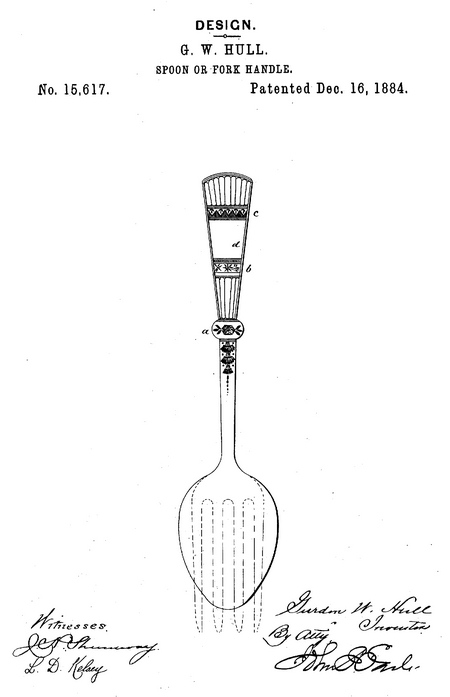
- Patent: 15,617, on 16 Dec 1884. GURDON W. HULL, OF WALLINGFORD, CONNECTICUT, ASSIGNOR TO SIMPSON, HALL, MILLER & CO., OF SAME PLACE.
DESIGN FOR A SPOON OR FORK HANDLE.
SPECIFICATION forming part of Design No. 15,617, dated December 16, 1884.
Application filed August 9,1884. Term of patent 14 years.
To all whom it may concern:
Be it known that I, Gurdon W. Hull, of Wallingford, in the county of New Haven and State of Connecticut, have invented a new Design for Spoon or Fork Handles; and I do hereby declare the following, when taken in connection with accompanying drawing, and the letters of reference marked thereon, to be a full, clear, and exact description of the same, and which said drawing constitutes, part of this specification, and represents a face view of a spoon, broken lines indicating the termination when made in shape of a fork, such termination, however, not constituting any portion of this invention.
This design relates to the ornamentation of the handles of spoons, forks, and like articles of table-service; and it consists in the ornamentation, as hereinafter described, and shown in the accompanying illustration. At about midway of the length of the handle is a boss, a. From the boss the handle gradually expands to the tip. The surface is bordered by a bead. Transversely across the face are two ornamental bands, b c, leaving a plain space, d, between them. On the surface between the boss a and the transverse band b the surface is reeded, the reeds gradually expanding in width from the boss to the band b. From the band c to the tip the surface is also reeded, as shown in the accompanying illustration. The boss a may be omitted entirely, or some other ornament inserted in place of it, this constituting no part of the present design.
I claim—
The herein-described design for the ornamentation of the handles of spoons and forks, consisting in the transverse bands b c across the face of the handle, the surface below the band h and above the band c reeded, as shown in the accompanying illustration.
Gurdon W. Hull
Witnesses:
Andrew Andrews
Charles D. Yale

- He was issued patent number 398,213 on 19 Feb 1889
HERBERT ATKINSON AND GURDON W. HULL, OF WALLINGFORD, CONNECTICUT; SAID ATKINSON ASSIGNOR TO SAID HULL.
WHISTLE.
SPECIFICATION forming part of Letters Patent No. 398,213, dated February 19, 1889. Application filed October 8, 1888, Serial No, 287,475, (No model.)
To all whom it may concern:
Be it known that we, Herbert Atkinson and Gurdon W. Hull, of Wallingford, in the county of New Haven and State of Connecticut, have invented a new Improvement in Whistles; and we do hereby declare the following, when taken in connection with accompanying drawings and the letters of reference marked thereon, to lie a full, clear, and exact description of the same, and which said drawings constitute part of this specification, and represent, in—
Figure 1, a side view of a handle with the whistle in the closed position; Fig. 2, a partial view of same, showing the whistle in the open position; Fig. 3, a transverse central section of Fig. 1; Fig. 4, a transverse central section of Fig. 2; Fig. 5, a transverse central section showing a modification in the construction of the whistle and as constructed for a pocket-whistle.
This invention relates to an improvement in whistles particularly adapted to handles for canes, whips, umbrellas, and like, articles, but applicable to other purposes, and may be used as an independent call or signal whistle. As usually constructed, the openings of the whistle are exposed and liable to become clogged, and when formed as part of a handle detract from the finished appearance of the handle.
The object of this invention is to produce a whistle in which in its normal condition the openings are closed and unexposed; and it consists in the construction as hereinafter described, and particularly recited in the claims.
I illustrate the whistle as made a part of a cane-handle.
A represents the body of the handle, which, as here represented, is hollow and made from metal, and closed near the outer end by a disk, a, but so as to leave a tubular recess in the end of the body, as seen in Fig. 3; or, in case the handle is solid, the recess is formed at the end, the said disk a representing the bottom of the recess. From the disk a, a spindle, b, extends outward, of a length corresponding to the desired length of the finished handle, and terminates with a head or button, d, Upon the spindle b a disk, e, is fixed in a plane at right angles to the axis of the spindle, but at a point outside the end of the body of the handle, and of a diameter less than the internal diameter of the body A.
B represents the tip of the handle, which is tubular. The external diameter of the inner end corresponds to the diameter of the recess in the body A, and so as to slide therein, contracted at its outer end, so that its internal diameter at the outer end corresponds to the diameter of the button d, and so that when in the closed position, as seen in Fig. 3, the button d closes the end of the tip B.
In the tip B a series of circumferential slots, /, are formed in such a position that when the head B is drawn out the outer edge of the slots will come into the plane of the disk e, which is of slightly less diameter than the internal diameter of the tip B, and so as to leave an annular opening between the disk e and the inner surface of the tip, as seen in Fig. 4.
To prevent the tip B from being drawn out, so that, the slots f will pass beyond the disk e, a longitudinal slot, y, is made in the inner portion of the tip B, and a stud, h, is arranged in the body A to project into the slot g, as seen in Figs. 3 and 4, and thereby stop the tip in its proper relation to the disk e.
In its normal or closed position the tip B rests in the body A, as seen in Figs. 1 and 3, held there by frictional contact. In operation the tip B is drawn out, as seen in Figs. 2 and 4, and so that, blowing into the tip B, the wind passes in over the button d and disk e, and impinging on the inner edge of the slot f, as indicated by arrows, Fig. 4, produces the whistling sound.
Instead of producing the whistle by an annular discharge of the wind against a practically-annular edge of the slots, after the manner of steam-whistles, the tip maybe provided with a single slot or opening, f, as seen in Fig. 5, and the spindle made accordingly, so that there will be a single opening from the open end of the tip to the slot to produce the sound; but in this case there is the same advantage of the sliding tip—that is, that the end of the tip is entirely closed when not in use and the whistling apparatus enclosed in the surrounding body.
By this construction a handle is produced which in its closed position may be the same in appearance as an ordinary handle, and one in which the whistle is in no way liable to become clogged.
While the construction of the whistle is especially designed for handles for canes, umbrellas, or like purposes, it will be evident that the tubular body and sliding tip maybe employed as a pocket-whistle, and as indicated in Fig. 5
We claim—
1. The herein-described whistle, consisting of the combination of the tubular body A, the tip B, arranged to slide longitudinally in said tabular body, the outer end of the tip open but contracted, an extension from the body within said tip and terminating at its outer end in a head corresponding to the contracted opening through the outer end of the tip, and so as to close the outer end of the tip when the tip is in the closed position, the tip constructed with one or more openings through it in such relation to the body that the openings in the tip are exposed only when the tip is drawn from the body, and the extension from the body provided with a disk of less transverse area than the interior of the tip at the openings and at a point corresponding to the outer edge of the opening when the tip is withdrawn, substantially as described.
2. The combination of the tubular body A, open at one end and closed at the opposite end, the tubular tip B, arranged to slide in the said tubular body and project through the open end, the body constructed with a spindle, b, projecting therefrom through the tip and terminating at its outer end in a head, d, of less diameter than the internal diameter of the tip, and the outer end of the tip contracted to an internal diameter corresponding to the said head, and so that in the closed position the said head will close the outer end, the spindle also constructed with a disk, e, in a plane at right angles to its axis within the tip and outside the open end of the body, the said disk of less diameter than the internal diameter of the tip, and the tip constructed with circumferential slots/ in such relation to the said disk e that when the tip is drawn out the outer edge of the slots will come into the plane of the disk, and a stop to arrest the outward movement of the tip when the slots of the tip have reached their proper position in relation to the disk, substantially as described.
H. Atkinson
G. W. Hull
Witnesses:
John R. Francis
Wm M. Whtttaker
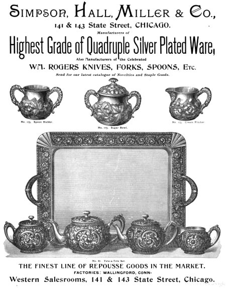
- Advertised: The Jewelers' Circular and Horological Review, in 1893.
Gurdon married Elizabeth Melinda Simpson, daughter of Samuel Simpson and Martha Deette Benham, on 6 Jun 1864 in Wallingford CT. (Elizabeth Melinda Simpson was born on 16 Aug 1839 in Wallingford CT and died on 20 May 1917 in Wallingford CT.)
|


