Virgil Draper
- Born: 24 Jul 1814, Attleboro MA
- Marriage (1): Ann Whiting Draper on 26 Nov 1838 in Attleboro MA
General notes:
Silversmith and jeweler
Events in his life were:
- He worked circa 1835-1880 as a silversmith and jeweler in Attleboro MA
- He appeared on the census in 1850 in Attleboro MA. Listed as a jeweler.
- He appeared on the census in 1855 in Attleboro MA. Listed as a jeweler.
- He appeared on the census in 1860 in Attleboro MA. Listed as a jeweler.

- He was issued patent number 80,535 on 4 Aug 1868
VIRGIL DRAPER, OF NORTH ATTLEBORO, MASSACHUSETTS, ASSIGNOR TO EDMUND J. RICHARDS, OF SAME PLACE.
Letters Patent No. 80,535, dated August 4, 1868.
IMPROVED APPARATUS FOR SWAGING THE SWIVEL-EYES OF WATCH-CHAINS.
TO ALL PERSONS TO WHOM THESE PRESENTS MAY COME:
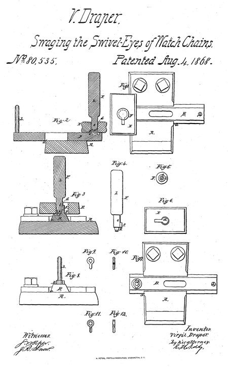
Be it known that I, Virgil Draper, of North Attleboro, in the county of Bristol, and State of Massachusetts, have invented a new and useful Machine for Forming the Blanks of Watch-Chain Swivel-Eyes ; and I do hereby declare the same to be fully described in the following specification, and represented in the accompanying drawings, of which—
Figure 1 is a top view,
Figure 2 a longitudinal section, and
Figure 3 a transverse section of it.
Figure 4 is a side view, and
Figure 5 a lower end view of the punch.
Figure 6 is a top view of the swaging-die plate.
Figure 7 is a top view, and
Figure 8 a side elevation of the sliding-bed die and its carrier, and the supporter thereof.
Figure 9 is a top view, and
Figure 10 an edge view of a swivel-eye blank, as made preparatory to being swaged and formed by the mechanism constituting my invention.
Figure 11 is a top view, and
Figure 12 an edge view of such blank as it appears after having been swaged and formed by the said. mechanism.
In the drawings, A denotes the supporter of the carrier B of the bed-die. This supporter has a dovetailed groove, a, made across it to receive the carrier B, which is a bar dove-tailed in transverse section, to fit to and slide through the groove a. A handle, b, extends up from the carrier.
The bed-die D is represented as arranged in a circular cavity, c, made in the carrier. This bed-die, formed as represented, projects, above the upper surface of the carrier, so as to enter the swaging opening d of the swaging-die plate E. Such opening, formed as represented in top view in fig. 6, tapers a little as it descends. The purpose of the said taper of the opening or die-collar is to gradually swage the eye-blank while passing through it, and, with the bed-die D and the punch F, reduce the said blank from the form, shown in figs. 9 and 10, to that described in figs. 11 and 12.
The main operative part of the punch consists not only of a cylinder, e, and a short prismatic projection, f, extending from the side of such cylinder, but of a short round pin, g, extending from the lower end of the cylinder. Such cylinder projects from a head or shank, h.
The mechanism.above described is to be used in a "drop-press." In using it, the carrier is first to be introduced into its supporter, after which the swaging-die plate should be arranged over the die of the carrier, so as to have the said die within the swaging opening of the said plate. Next, the blank is to be placed over the said opening, and the part g of the punch should be introduced into the blank. Next, one or more powerful blows are to be given upon the head of the punch, so as to force the blank into the swaging-die, and down upon the bed-die, and reduce the said blank to the form exhibited in figs. 11 and 12.
Next, the die-plate E, with the punch in it, is to be raised off the bed-die, and the carrier is to be drawn back, so as to allow the die-plate to rest on the supporter A. Next, the punch is to be forced down so as to expel the swaged blank from the opening of the die-plate, and into the dove-tailed groove a, after which the die-plate and punch are to be raised off the supporter, and the carrier is to be advanced to place for again co-operating with the die-plate and punch, in manner as hereinbefore described. The advance of the carrier operates to force the swaged blanks along through the groove a, and crowd them off the supporter.
I claim the combination of the grooved, supporter A, the carrier B, the bed-die D, the swaging-die plate E, and the punch F, such being constructed for use in manner and for the purpose substantially as described.
Virgil Draper
Witnesses
Wlllard W. Albee
Thos. G. Sandland
- He appeared on the census in 1870 in Attleboro MA. Listed as a jeweler.

- He was issued patent number 210,303 on 26 Nov 1878
VIRGIL DRAPER, OF NORTH ATTLEBOROUGH, MASSACHUSETTS.
IMPROVEMENT IN GEM-SETTINGS.
Specification forming part of Letters Patent No. 210,303, dated November 26, 1878; application filed August 12, 1878.
To all whom it may concern:
Be it known that I, Virgil Draper, of North Attleborough, in the county of Bristol and State of Massachusetts, have invented certain new and useful Improvements in Jewelry; and I hereby declare that the following is a full, clear, and exact description of the same, reference being had to the accompanying drawings, forming part of this specification.
This invention relates to improvements in jewelry; and consists in the peculiar construction and arrangement of the jewel clamps or holders, as will hereinafter more fully appear from the following description and claims.
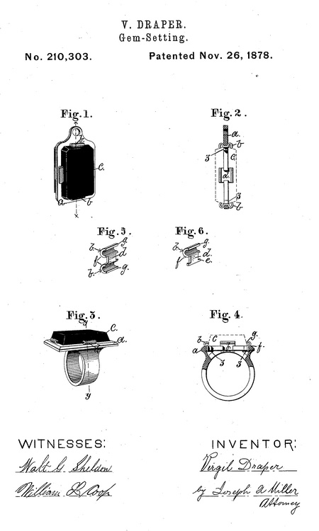
Referring to the drawings, Figure 1 is a perspective view of a charm in which two stones are secured by my improved clamps. Fig. 2 is a sectional view of the charm shown in Fig. 1 through line x x, and shows how the clamps may be inserted and made so as secure two settings. Fig. 3 is a perspective view of a ring in which a stone or gem is secured by my improved clamps. Fig. 4 is a sectional view through line y y of the ring shown in Fig. 3, and shows how a single stone is secured by these clamps; it also clearly shows how the curved clamp firmly rests on the frame, and, when the edge of the clamp is set against the stone, how firmly the clamp is braced and the stone held. Fig. 5 is a perspective view of the double clamp, and Fig. G of the single clamp.
In the drawings, A represents the frame of any piece of jewelry; b, my improved clamp, which consists in a semicircular curved piece of metal secured so as to rest on the frame at a point marked f, so that the stone or gem can be passed between the clamps, (any number of which may be used,) and when the stone is properly placed the edge g is pressed firmly against the stone, and by this pressure the portion of the clamp at f is also firmly pressed against the frame, and a clamp even of thin metal is thus so firmly braced between the frame and the stone that the stone cannot get loose until extra force is exerted, and a stone or gem is thus more firmly secured than in the old manner, and much better displayed. C represents a stone or gem. When two stones or gems are secured to a frame, the double clamp shown in Fig. 5 is used. This consists of two clamps united by the piece d, which I prefer to set into a slot, 2, so that the clamps proper form shoulders, and when set against the stone or gem they will be firmly held, and the frame and gem firmly secured together.
In the single clamp I provide a shoulder, e, to hold the clamp in the frame.
The clamps may be dovetailed or secured in any manner by solder; and, instead of forming semi-tubes the clamps maybe made of wire of any desired section, curved in a semicircle, and arranged so that when pressed against the stone or gem they will form a curved brace, resting on the frame and pressing against the stone or gem, as is clearly shown in Figs. 2 and 4 of the accompanying drawings.
Having thus described my invention, I claim as new and desire to secure by Letters Patent—
1. The combination, with the plate a, having any desired number of notches formed on its inner edge, of jewel-clamps, each formed with a shank which fits into one of said notches, shoulders on the lower end of the shank which rest against the lower surface of the plate, and the upper end of the clamp being outwardly bent to rest upon the upper surface of the plate, while the upper portion is of semicircular form, substantially as set forth.
2. The combination, with the plate a, of jewel-clamps, the lower ends of which are secured against the inner edge of said plate, while the upper ends are semicircular in form and rest upon the upper surface of said plate, substantially as set forth.
3. A gem or jewel clamp made with two semicircular clamps, h, united by the piece (7, and arranged to be secured in a slot of the frame, so as to hold two stones or gems on opposite sides of the frame, substantially as and for the purpose set forth.
4. The combination, with the plate a, of a sheet-metal clamp having its lower end secured to the inner edge of the plate, while its upper portion is bent outwardly and the upper end bent inwardly and forced downwardly against the outwardly-inclined faces of the jewel, substantially as set forth.
Virgil Draper
Witnesses:
Joseph A. Miller
Joseph A. Miller, Jr.
- He appeared on the census in 1880 in Attleboro MA. Listed as a jewelry manfacturer.

- He was issued patent number 294,595 on 4 Mar 1884
VIRGIL DRAPER, OF NORTH ATTLEBOROUGH, MASSACHUSETTS.
ORNAMENTAL CHAIN-LINK.
SPECIFICATION forming part of Letters Patent No. 294,595, dated March 4, 1884.
Application filed November 13, 1883.
To all whom it may concern:
Be it known that I, Virgil Draper, of North Attleborough, in the county of Bristol and State of Massachusetts, have invented a new and useful Improvement in Ornamental Chain-Links; and I hereby declare the following to be a full, clear, and exact description of the same, reference being had to the accompanying drawings, forming part of this specification.
This invention has reference to an improvement in the construction of ornamental chain-links; and it consists in the novel arrangement of the parts by which the stamped sides of the link are secured together by the end sleeves and held in place by the connecting-rings, as will be more fully set forth hereinafter.
In the manufacture of ornamental chains, lightness, combined with a high order of ornamentation, is the essential requisite, and when such ornamental chains are made of inferior metal plated with a precious metal or fire-gilded it is important that each separate piece can be gilded and burnished before they are secured together to form the link, and that no solder or heat is used, as the heat will injure the color and polish of the parts.
The object of this invention is to so construct an ornamental chain-link that the sides can be shaped and ornamented in suitable dies, the parts gilded and polished, and then secured together without heat or solder.
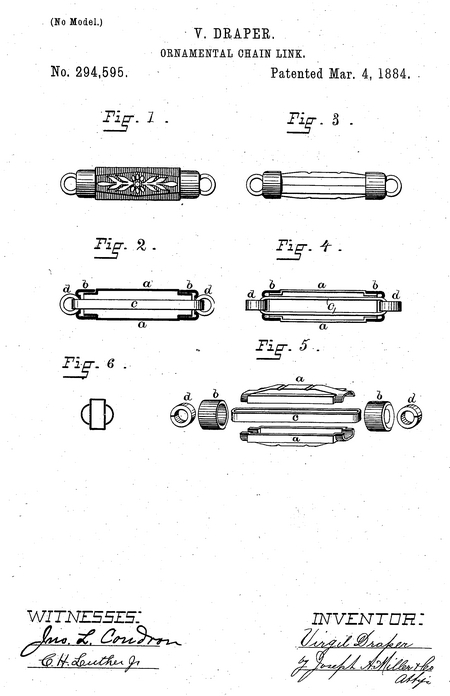
Figure 1 is a view of one style of ornamental chain-link constructed after my present invention. Fig. 2 is a sectional view of the same. Fig; 3 is a side view of another style of ornamental chain-links. Fig. 4 is a sectional view of the same. Fig. 5 is a perspective view of the parts forming an ornamental chain-link placed so as to show the same clearly and in their relative positions. Fig. 6 is a cross-section of the chain-link.
In the drawings, a a are staves, which form the ornamental sides of the chain-link. These sides may be made in two pieces, so as to form the two halves of the link, or they may be made in three, four, or more pieces, according to the form or ornamentation desired, and so that each piece can be readily formed in suitable dies, gilded, and polished. These sides a a or staves are secured together like the staves of a barrel.
b b are the end caps or sleeves, which are placed over the ends of the sides a a and secure the same together.
C is a loop which is placed into the chain-link and extends from end to end of the same.
d d are two rings which are placed into the ends of the loop c, and bear against the caps or sleeves b b, thereby firmly locking all the parts together.
By this construction all the parts of the ornamental link are secured together without the use of solder or heat, and all the parts can be finished separately before the same are formed into the link or chain.
The chains are formed, in the usual manner, by connecting the rings d of two links by a connecting-ring.
I am aware that heretofore chain-links have been made of two or more side pieces surrounding a central link or loop and held by end caps; hence I do not broadly claim such structure.
Having thus described my invention, I claim as new and desire to secure by Letters Patent—
The combination, with the link or loop c and rings d, of the staves a and the circular caps b, fitting over the ends of said staves, as described.
Virgil Draper
Witnesses:
Joseph A. Miller
Joseph A. Miller, Jr
Virgil married Ann Whiting Draper, daughter of Samuel Origen Draper and Nancy Whiting, on 26 Nov 1838 in Attleboro MA. (Ann Whiting Draper was born on 26 Oct 1817 in Attleboro MA.)
|


