Garry Ives Mix
- Born: 31 Aug 1819, Wallingford CT
- Marriage (1): Almira White on 7 Dec 1842 in Wallingford CT
- Died: 13 Aug 1892, New Haven CT
General notes:
Pewtersmith
Events in his life were:
- He worked in 1845-1854 as a pewtersmith in Wallingford CT 31
- Partnership: Charles E. Parker, in 1848, in Yalesville CT. Manufacturing and plating flatware.
- He appeared on the census in 1850 in Wallingford CT. Listed as a spoon maker.
- He worked in 1854-1860 as a pewtersmith in Yalesville CT 31

- He was issued patent number 18,513 on 27 Oct 1857
G. I. MIX, OF WALLINGFORD, CONNECTICUT.
MAKING IRON SPOONS.
Specification forming part of Letters Patent No. 18,513, dated October 27, 1857; Reissued August 8, 1871, No. 4,506.
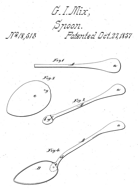
To all whom it may concern: Be it known that I, G. I. Mix, of Walling- ford, in the county of New Haven and State of Connecticut, have invented a new and useful Improvement in the Construction of Iron Spoons; and I do hereby declare that the following is a full, clear, and exact de- scription of the same, reference being had to the accompanying drawings, making a part of this specification, in which— Figure 1 is a detached view of a handle, partially completed. Fig. 2 is a detached view of the same, fully completed. Fig. 3 is a detached view of a blank, of which the bowl is formed. Fig. 4 is a view of a spoon completed.
Similar letters of reference indicate the same parts in the four figures.
The nature of my invention consists in having the rivet or pin which secures the handle and bowl together, formed on the handle at the same time and by the same die which gives form to the handle, and thus instead of having to insert a rivet one is already provided which forms part and parcel of the handle, and is more firm on account of but one end being separated from the metal forming the spoon, this mode of constructing spoons providing an improved article of manufacture, to wit: an iron spoon with the rivet forming part and parcel of the handle.
Irons spoons as at present or hitherto made are an exceedingly rude article, merely forged out and tinned, the marks of the hammer being distinctly visible when finished. My improved spoons are fully equal in appearance to those made of the more expensive metals or compositions. To enable those skilled in the art to fully understand and construct my invention, I will proceed to describe it.
I construct the handle A of the spoon of a piece of iron wire of the requisite thick- ness and length. One end of this wire is swaged by means of proper dies or rollers, to form the usual flattened outer end of the handle, as shown at (a) in Fig. 1. The opposite or inner end of the handle A is also flattened, as shown at (&) in Fig. 2, and is provided with a shoulder (e). The inner end of the handle is also curved, as shown at (d) in Fig. 4.
The bowl B of the spoon is formed by cutting an oval plate or blank (e) Fig. 3 out of a piece of plate iron and then striking (by means of dies) said blank or plate into the usual concave form, as shown in Fig. 4. The inner end of the handle A, the flat- tened portion (6), has a pin (f). and this flattened portion (b). is fitted to the inner end of the bowl B, the pin (f) passing- through a hole (g) in the bowl. The pin (f) is then riveted and the part (b) brazed, soldered or welded to the bowl.
The spoon thus constructed is exceedingly neat, and when tinned or galvanized it forms a spoon fully equal in appearance to any manufactured.
Tinned or galvanized iron spoons are far preferable to German silver and other com- positions used for such purposes. German silver soon tarnishes or turns yellow and resembles brass; besides, compositions leave an unpleasant taste in the mouth.
Iron spoons have not been hitherto used for table purposes, for being made by hand and forged they could not, without great expense, be finished neatly. Hence the iron spoons constructed hitherto are intended for kitchen use only; but by my improved construction they will compare favorably with any now manufactured.
I would remark that the pin (f) is a part and parcel of the handle, raised on the flattened part (b) by means of a hole in the upper die which flattens the inner end of the handle.
What I claim as my invention and desire to secure by Letters Patent, is— Having the rivet or pin which secures the handle and bowl of the spoon together, formed on the handle at the same time and of the same piece of metal, by the same die which gives form to the handle; whereby an improved article of manufacture is provided, to wit: an iron spoon with the rivet forming part and parcel of the handle, substantially as and for the purposes herein set forth.
G. I. Mix
Witnesses:
E. J. Ives,
Birdsey Beistel
- He appeared on the census in 1860 in Wallingford CT. Listed as a manufacturer of spoons.
- He worked in 1860-1880 as a pewtersmith in Wallingford CT 31

- Patent: 31,555, on 26 Feb 1861. G. I. MIX, OF WALLINGFORD, CONNECTICUT.
IMPROVEMENT IN MANUFACTURE OF SPOONS.
Specification forming part of Letters Patent No. 31,555, dated February 26, 1861.
To all whom it may concern:
Be it known that I, G. I. Mix, of Wallingford, in the county of New Haven and State of Connecticut, have invented a new and useful Improvement in Wiring and Strengthening Cast-Metal Spoons; and I do hereby declare that the following is a full, clear, and exact description of the same, reference being had to the annexed drawings, making a part of this specification, in which—
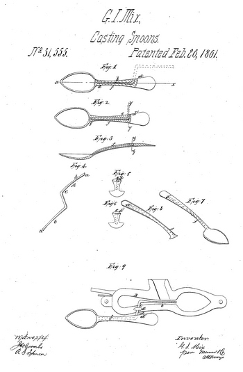
Figure 1 is a face sectional view of my invention. Fig. 2 is a face sectional view of a spoon wired in the ordinary way. Fig. 3 is a longitiidinal section of Fig. 1, taken in the line x x. Fig. 4 is a detached, perspective view of the wire used in my invention. Fig. 5 is a transverse section of Fig. 2, taken in the line y y. Fig. 6 is a transverse section of Fig. 3, taken in the line z z. Fig. 7 is a perspective view of a spoon wired according to my invention. Fig. 8 is a perspective view of the handle of a spoon wired in the ordinary way. Fig. 9 is a plan or top view of the lower part of the mold in which the spoons are cast, showing the manner in which the wire is inserted in the mold.
Similar letters of reference indicate corresponding parts in the several figures.
Spoons which are cast of soft metal require to have their handles strengthened by a wire, and. these wires have hitherto been round and fitted in the mold by means of pliers, the metalbeing cast around the wire in the mold. The ordinary mode of wiring is attended with some disadvantages. The first is, that the wire being round or cylindrical weakens the handle at its upper part, where it is broad and flat, as the wire allows but a small mass of metal at that point, and nearly divides the handle for a distance of half its width. The second disadvantage is, that the round or cylindrical rod or wire admits of the handle of the spoon bending after being cast, as the metal will slip over or around it, and consequently a cavity will be left or allowed in the handle at its junction with the bowl, and this, cavity greatly weakens the spoon at the point specified. The third disadvantage is, that the wire being adjusted in the mold by pliers considerable time is expended in the proper prosecution of this work. My invention obviates all of these difficulties, as will hereinafter appear.
To enable those skilled in the art to fully understand and construct my invention, I will proceed to describe it. A represents a piece of wire of suitable dimensions and bent in a zigzag form, as shown clearly in Fig. 4. This wire is of flat form, and its ends a a are flattened out broader than at points b above it, and the center part, c, of the wire is also made flatter. This piece of wire A forms the wire for two spoons, but it is not divided until after the spoons are cast. The mold B, which is shown in Fig. 9, may be of the usual construction, and one-half of the wire is adjusted in the mold, as shown in the said figure, one of the ends a being at the junction of the handle and bowl, and the flat part c passing out at the side of the mold. By this arrangement it will be seen that one part of the wire A will serve as a handle to adjust the other part in the mold B, and when a spoon is cast on one part of the wire A, the spoon will serve as a convenient handle to adjust the other part of the wire in the mold to cast a succeeding spoon, as will be fully understood by referring to Fig. 9. The wire A may be held in proper position in the mold by a clamp, d, arranged in any proper way. The flat part c of the wire, it will be seen, passes out at the upper and flat part, d', of the handle, and consequently does not weaken the handle i n the least, (see Figs. 6 and 7,) while the round rod or wire e hitherto used greatly weakens said part d', as will be seen by referring to Figs. 5 and 8. The central part, /, of the handle of the spoon being thicker and approximating to a spherical form, the wire A has its part & rat her thicker than elsewhere, in order to give the handle of the spoon the requisite degree of stiffness.
When a spoon is cast with my improved form of wire, it will be seen that the handle cannot slip longitudinally over the wire, for the broad terminals a will prevent it. This result generally adds to the stiffness of the handle. The round or cylindrical wire e being of equal diameter throughout; will admit of the metal of the handle slipping over it longitudinally as the handle is bent. This result causes an opening or cavity at the lower part of the handle at its junction with the bowl, as shown at g in Fig. 2, and consequently the spoon will be much weakened at this point as well as at the upper part of the handle, d'. My invention not only obviates these difficulties, but also greatly facilitates the casting of the spoons, as the wires A may be adjusted in the mold very expeditiously and in a very accurate manner. The wires being struck between two steel-tempered dies to give them their thin form, are of course perfectly uniform, the mold being fitted to them so that when the beak or clamp is brought down on the wire it uniformly finds a central position in the mold without any adjusting, which enables the caster to throw out at least onethird more spoons per clay than by the old way, in which each wire has to be very carefully fixed after it is put into the mold before the caster is prepared to pour the metal. It may be too high or too low, and frequently so much time is lost that the mold cools off so much that the casting will be imperfect. By my invention the spoons need no other manipulations after they are cast than to cutoff the flattened wire close to the handle before they go to be polished and finished in the ordinary way. Spoons have been cast with a wire or rod round, square, or flat, running the whole length of the handle, and they have been cast hollow and a wire afterward put into the cavity. In all the above modes it was necessary to cast the handle larger than the finished article was designed to be, and the handle pressed into shape with dies, and the excess of metal driven out at the sides and then clipped off.
In all the old modes, including the old way of turning the wire out at the sideshort of the end of the handle, there is at least from threefourths of an inch in length to one-fourth inch more wire wasted than in my improved way, which makes a very imperfect stem.
I do not claim, broadly, the casting of spoons with strengthening wires in the handles; but, Having thus described my invention, what I claim as new, and desire to secure by Letters Patent, is—
The employment, in the manner and for the purpose herein shown and described, of the zigzag wire A, formed as set forth, in combination with the molds B and spoons ff, all as specified.
G. I. Mix
Witnesses:
Ebenezer H. Ines,
Theodore F. Lane.

- He was issued patent number 58,665 on 9 Oct 1866
G. I. MIX, OF YALESVILLE, CONNECTICUT.
IMPROVEMENT IN THE MANUFACTURE OF SPOONS.
Specification forming part of Letters Patent No. 58,665, dated October 9, 1866.
To all whom it may concern:
Be it known that I, G. I. Mix, of Yalesville, in the town of Wallingford, county of New Haven, and State of Connecticut, have invented a new and useful Improvement in the Manufacture of Spoons, Forks, Ladles, and other articles of similar character; and I do hereby declare that the following is a full, clear, and exact description of the same, reference being had to the accompanying drawings, forming part of this specification.
The common method of manufacturing spoons of silver, German silver, albata, and other hard alloys, is, first, to cast the metal or alloy into ingots of suitable size; next, to roll out the ingots into sheets of a uniform thick ness, equal to what is required for the narrower and thicker portions of the shanks.
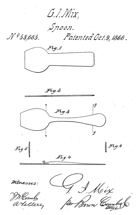
These sheets are then cut into blanks of a form substantially like that shown in Figs. 1 and 2, which represent, respectively, a plan and an edge view, such blanks being shorter than the spoon, and in some parts wider. The blanks are afterward drawn down between rolls of suitable shape to bring them to the proper thickness in the several parts, and then trimmed in dies preparatory to the final stamping process by which they are shaped.
Several rolling operations are necessary to reduce the ingots to sheets of the requisite thickness; and between the successive rolling operations the metal has to be frequently an nealed and scraped.
Much labor and a large consumption of fuel for heating are involved in the above method of manufacture, and besides this there is much loss of material, for more than half the stock is cut into scraps by the first cutting out and subsequent trimming operations; and although this scrap is remelted and rolled out again, there is considerable waste in remeltiug.
Furthermore, there is much waste, owing to the flaws which result from frequent rolling, the flaws having to be scraped out; and in many cases there are flaws which render the entire blank worthless, except as stock for reworking. These remarks apply also to the manufacture of forks, ladles, &c.
The object of this invention is to reduce the great labor, consumption of fuel, and waste of stock involved in the above process, and to produce goods of better quality; and to this end the invention consists in casting the metal (preparatory to rolling) into blanks of such form and varying thickness that but little rolling is required to bring them to the required shape for finishing.
Figure 3 is a plan, and Fig. 4 an edge, view, and Figs. 5 and 6 transverse sections, in the lines xx and yy, of a spoon-blank obtained by casting as in my process.
It will be observed by reference to Fig. 3 that the blank is in its various parts of a width approximating to what is required for the spoon; and by reference to Fig. 4, that it is made with the swell a, necessary for strength, at the junction of the shank with the bowl, this swell extending some distance into the bowl part, the blank tapering from the said swell all the way to the head or extremity of the handle; also, that the blade is made thicker at the point where the greatest thickness is required in a well-made spoon.
The blanks may be cast in molds-of cast-iron, sand, or other material employed for molds, according to the kind of metal or alloy of which the spoons are made. The cast blanks are rolled sufficiently to bring them to the proper shape for trimming and finishing, and to give the metal the necessary toughness and solidity. By thus casting the blanks, not only are they enabled to be finished with but little rolling, but there is very little waste of stock in trimming, and the whole expense of rolling into sheets is saved.
By this mode of manufacturing the spoons they can as easily be made thick as thin at the junction of the shank with the bowl and through the narrow partof the handle; whereas, owing to the great expense that would be involved in the subsequent rolling if the sheets from which the blanks are cut were made very thick at that point, few or none of the spoons made in this country are made as strong as de sirable at that point, and the consequence is that the stronger kinds of spoons—for hotels, ships, and steamers—are imported.
What I claim as my invention, and desire to secure by Letters Patent, is—
The spoon, blank cast and subsequently rolled, as described, as an article of manufacture.
G. I. Mix
Witnesses:
Henry T. Brown
J. W. Coombs
- General: 1868. Member of Connecticut state senate for the 6th District. 31
- He appeared on the census in 1870 in Wallingford CT. Listed as a spoon manufacturer.
- He appeared on the census in 1880 in Wallingford CT. Listed as a manufacturer of spoons.

- Patent: 18,290, on 1 May 1888. GARRY I. MIX, OF YALESVILLE, CONNECTICUT
DESIGN FOR A SPOON
Specification forming part of Design No. 18,290, dated May 1, 1888. Application filed November 30, 1887. Serial No. 256,571. Term of patent 14 years
To all whom it may concern.
Be it known that I, Garry I. Mix, of Yalesville, in the county of New Haven, and in the State of Connecticut, have invented a certain new and useful Design for Spoons; and I do hereby declare that the following is a full, clear, and exact description thereof, reference being bad to the accompanying drawings, in which —
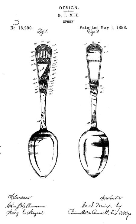
Figure 1 is a front elevation of a spoon having my design, and Fig. 2 is a rear elevation of the same.
Letters of like name and kind refer to like parts in each of the figures.
The principal feature of my design consists in a band, a, which extends in a curve across the upper end of the handle of the spoon A, is defined by raised beads a1 and a1 at its upper and lower edges, and has at suitable points upon its face star-shaped figures a2 and a2. The face of said band is ornamented by a series of equidistant parallel lines.
Another feature of my design consists in a band, a3, which extends in a curve across the central portion of the handle of the spoon, with its upper and lower edges defined by elongated bead-like projections a4 aud a4, and upon its face has a number of semi-spherical protuberances, a5 and a5, that are centrally arranged in a line corresponding to the curvature of said band. The face of said baud is also ornamented by a series of equidistant parallel lines.
Another feature of my design consists in a raised line, a6, which extends along each edge of the upper portion of the spoon handle and connects the bands a and a3.
Another feature of my design consists in a band, a', which extends in a straight line across the spoon-handle near its upper end, with its face ornamented by a series of equidistant parallel lines and its edges defined by two raised beads, a8 and a8, and upon its face a number of star-shaped figures, a9 and a9.
Another feature of my design consists in a band, a10, which extends in a curve across the handleof the spoon, with its upper edge defined by a raised bead, a11, and its lower edge by the row of bead-like projections a4 and a4. Said band is ornamented by a number of leaves, a12 and a12, which extend from its lower edge upward, and a flower and stem, a13, that extends upward from between the contiguous edges of said leaves. The face of said band is cross-hatched, as shown.
Another feature of my design consists of a panel, a14, which extends betweens the bands a1 and a10, and is divided by a band, a15, that extends diagonally across the same from its upper end to its lower end. Said band a15 is ornamented by a series of transversely arranged parallel lines, and has extending lengthwise of the same a vine, a16. In one of the lower corners of said panel is a fan-shaped figure, a17, while across its upper end is a row of bead-shaped protuberances, a18.
Another feature of my design consists in a panel, a19, which extends between the bands a and a7 and has its surface ornamented by vertically-arranged half-round ribs a20 and a20.
Another and the last feature of my invention consists in the entire design, as herein shown and described.
Having thus described my invention, what I claim is—
1. The design for a spoon handle herein shown and described, the same consisting of the panel a14, which is divided by the diagonal band a15, having the vine a16, and has the fan-shaped figure a17 placed in its lower corner and the row of beads a18 across its upper end, substantially as set forth.
2. The design for a spoon-handle herein shown and described, the same consisting of the entire ornamentation, substantially as set forth.
In testimony that I claim the foregoing I have hereunto set my hand this 27th day of September, 1887.
Garry I. Mix
Witnesses:
W. A. Kendrick
E. S. May
Garry married Almira White on 7 Dec 1842 in Wallingford CT. (Almira White was born on 22 Nov 1819 in Middletown CT.)
|


